16
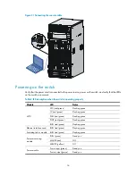
Figure 21
Connecting the console cable
Powering on the switch
Verify that the power cord is connected to the power source, power on the switch, and verify that the LEDs
on the switch are normal.
Table 2
LED description when the switch is operating properly
Module LED
Status
MPU
SFC (red/green)
Flashing green
LC (red/green)
Flashing green
FAN (red/green)
Flashing green
PWR (red/green)
Flashing green
RUN (red/green)
Flashing green
Ethernet interface card
RUN (red/green)
Flashing green
Switching fabric module RUN (red/green)
Flashing green
Power monitoring
module
RUN (green)
Steady on
MAJOR (red)
Off
MINOR (yellow)
Off
Power module
Power input (green)
Steady on
Power output (green)
Steady on


