background image

H3C S12500 Routing Switch Series

Installation Guide


Hangzhou H3C Technologies Co., Ltd.  
http://www.h3c.com 
 
Document version: 6W115-20130308


Summary of Contents for S12500 Series

Page 1: ...H3C S12500 Routing Switch Series Installation Guide Hangzhou H3C Technologies Co Ltd http www h3c com Document version 6W115 20130308...

Page 2: ...d All other trademarks that may be mentioned in this manual are the property of their respective owners Notice The information in this document is subject to change without notice Every effort has bee...

Page 3: ...s shown Italic Italic text represents arguments that you replace with actual values Square brackets enclose syntax choices keywords or arguments that are optional x y Braces enclose a set of required...

Page 4: ...or supplementary information TIP An alert that provides helpful information Network topology icons Represents a generic network device such as a router switch or firewall Represents a routing capable...

Page 5: ...Command references Provide a quick reference to all available commands Operations and maintenance System log messages Explains the system log messages Trap messages Explains the trap messages MIB Com...

Page 6: ...Documentation feedback You can e mail your comments about product documentation to info h3c com We appreciate your comments...

Page 7: ...Space 21 Rack mounting 22 Installation tools 23 Installing the switch 25 Confirming installation preparations 26 Installing an impedance carrier optional 26 Installing a chassis air filter optional 27...

Page 8: ...Managing the power supply system 64 Displaying the electrical label data for the power monitoring module 64 Enabling power supply management 65 Configuring the number of redundant power supplies 65 Ma...

Page 9: ...eplacing a transceiver module 103 Regulatory Compliance and Safety Information 105 Regulatory Compliance Information 105 Regulatory Compliance Standards 105 European Directives Compliance 106 USA Regu...

Page 10: ...the AC power supply to a power strip with lightning protection 140 Installing a lightning protector for a network port 141 Appendix E Engineering labels 143 Labels for cables 143 Labels for signal cab...

Page 11: ...8 9 S12518 DC 2 18 9 NOTE The line processing unit LPU slots are for both Ethernet interface cards and OAA cards For card specifications see Appendix A Technical specifications Unless otherwise specif...

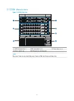
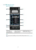
Page 12: ...S12504 front view 1 MPU slots slots 0 to 1 2 LPU slots slots 2 to 5 3 Power frame cover 4 Power switch cover 5 ESD preventive wrist strap port NOTE The power frame cover protects the power frame air f...

Page 13: ...The S12504 chassis has the following slots and components Two MPU slots and four LPU slots at the front and four switching fabric module slots at the rear One power frame at the bottom of the chassis...

Page 14: ...cabling rack 3 MPU slots slots 0 and 1 4 Lower cabling rack 5 Chassis air intake vents 6 ESD preventive wrist strap port 7 LPU slots slots 2 to 9 8 Power switch cover NOTE The power frame cover protec...

Page 15: ...ust vents 9 Power supply air exhaust vents The S12508 chassis has the following slots and components Two MPU slots and eight LPU slots at the front and nine switching fabric module slots at the rear O...

Page 16: ...Figure 5 S12518 front view 1 Power frame cover 2 Upper cabling rack 3 MPU slots slots 0 and 1 4 LPU slots slots 2 to 19 5 Lower cabling rack 6 Chassis air intake vents 7 ESD preventive wrist strap por...

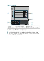
Page 17: ...fan tray 3 Switching fabric module slots slots 20 to 28 4 Lower fan tray 5 Ventilation panel 6 Grounding screw 7 ESD preventive wrist strap port 8 Chassis air exhaust vents 9 Power supply air exhaust...

Page 18: ...contains fan units The dimension of each fan unit is 120 120 38 mm 4 72 4 72 1 50 in An S12504 uses one fan tray which comprises eight fan units and one fan monitoring board An S12508 or S12518 uses...

Page 19: ...g properly ALM Off The fan tray is in a normal state Flashing The fan tray is faulty Steady on The fan tray is faulty Power supply system The S12500 switches provide both AC powered chassis and DC pow...

Page 20: ...AC power frame Each AC power frame can have one power monitoring module and up to six AC power supplies Figure 10 Front view of an AC power frame 1 to 6 AC power supplies the serial numbers are identi...

Page 21: ...front and exhaust warm air out of the rear Multiple AC power supplies work in N 1 or N M redundancy and support load balancing Figure 11 AC power supply 1 Power input LED 2 Power output LED 3 Over tem...

Page 22: ...ower monitoring module callout 7 in Figure 10 monitors the alarm status in position status and operating status of the power supplies in real time It is located between the power supply slot area and...

Page 23: ...C power supplies Figure 13 DC power frame front view 1 to 6 DC power supplies 7 Power monitoring module 8 Power monitoring module LEDs 9 Power frame switch Table 3 describes the LED behaviors of the p...

Page 24: ...er supply specifications Item Description Rated input voltage range 48 VDC to 60 VDC Max input voltage range 42 VDC to 72 VDC Startup voltage range 44 VDC to 72 VDC Max input current 60 A Max output p...

Page 25: ...s missing safety grounds and wet floors Locate the emergency power off switch in the room before installation Shut the power off at once in case accident occurs Unplug all the external cables includin...

Page 26: ...these guidelines Remove all the external cables including the power cables before moving the chassis For personal safety have several persons to move the switch carefully When moving the switch hold...

Page 27: ...ration of the switch make sure the room temperature meets the requirements described in Table 8 Table 8 Temperature requirements Temperature Range Operating temperature Long term 0 C to 40 C 32 F to 1...

Page 28: ...MI sources from outside or inside of the switch and application system adversely affect the switch in a conduction pattern of capacitance coupling inductance coupling electromagnetic wave radiation or...

Page 29: ...er source of the installation site is steady and can meet the requirements of the power supplies including the input method and rated input voltage For the power consumption and power supply specifica...

Page 30: ...re 18 Airflow through an S12508 chassis 1 Air intake direction of the chassis 2 Air exhaust direction of the chassis 3 Air intake direction of the power supplies 4 Air exhaust direction of the power s...

Page 31: ...19 Airflow through an S12518 chassis 1 Chassis air intake vents 2 Chassis air exhaust vents 3 Power supply air intake vents 4 Power supply air exhaust vents Space For easy maintenance follow these gu...

Page 32: ...other devices Rack mounting To mount the switch in a rack adhere to the following requirements Use a four post 19 inch standard rack The distance between the left and right rack posts is 465 mm 18 31...

Page 33: ...lation Accessories supplied by the switch Item Quantity Purpose Console cable 1 Connecting the console port and the configuration terminal for switch login Grounding cable 1 Grounding the switch Mount...

Page 34: ...ker Tape Diagonal pliers wire stripping pliers and wire clippers Socket wrench Cables such as network cables and fiber cables Meters and equipment such as hub and multimeter Configuration terminal suc...

Page 35: ...dily injury do not touch any wire terminal or part marked with a high voltage hazard sign Figure 22 Hardware installation flow NOTE For the S12504 the impedance carrier expansion cable management brac...

Page 36: ...nformation see Regulatory compliance and safety information Installing an impedance carrier optional An impedance carrier is shipped with each S12508 and S12518 switch You can install the impedance ca...

Page 37: ...alling an air filter on an S12518 Installing an air filter on an S12508 To install the front air filter on an S12508 1 Holding the notches of the front plastic panel at the bottom part of the chassis...

Page 38: ...of chassis cable management brackets You can select either type as needed Cable management brackets Shipped with the switch For more information see Product overview Expansion cable management bracket...

Page 39: ...he two sides of the front panel pivot the power frame front panel upward 3 Loosen the fastening screws on the upper cable management bracket with a Phillips screwdriver 4 Align the keyhole standoffs o...

Page 40: ...30 Figure 28 Installing an upper expansion cable management bracket 1 2 3 4 5 6 7...

Page 41: ...dles at both sides of the chassis Do not hold the plastic panel of the chassis the handle of the fan tray the handle of the back cover of the chassis or the air vents of chassis Any attempt to carry t...

Page 42: ...the slide rail with the corresponding mounting holes on the right rack posts and then fasten the screws 3 Repeat steps 1 and 2 to install the other slide rail to the left rack posts Keep the two slide...

Page 43: ...3 Figure 30 Installing the cage nuts Installing the mounting brackets Attach the mounting brackets onto the left and right sides of the switch Figure 31 Installing the mounting brackets for the S12504...

Page 44: ...tch To maximize the stability of the rack mount the heaviest switch at the bottom of the rack when you install multiple switches on the rack To mount the switch in the rack 1 Use several persons to pl...

Page 45: ...tion is completed check the installation against the following checklist Make sure all check results are positive Table 12 Installation checklist Item Result Remarks Yes No The mounting brackets are f...

Page 46: ...s of the switch and steadily move the switch to the workbench 2 Lift the switch a little higher than the workbench and put it on the workbench 3 Install the mounting brackets on the switch and fasten...

Page 47: ...pped with a grounding strip You can connect the yellow green grounding cable of the switch to the grounding strip CAUTION Connect the grounding cable to the earthing system in the equipment room Do no...

Page 48: ...r cords see Connecting power cords Installation preparation CAUTION Hold a power entry module PEM or power supply by the bottom when moving it Never attempt to lift a PEM or power supply with its hand...

Page 49: ...ver up with both hands 2 Pull the clip at the bottom left corner of the power supply to the left to open the power supply panel 3 Insert the power supply slowly into the slot until it is firmly seated...

Page 50: ...ing a PEM NOTE Gently insert the PEM into the chassis to avoid damaging the connector at the end of the PEM Installing an AC power supply IMPORTANT Make sure the number of power supplies is sufficient...

Page 51: ...e to the module The S12504 has one fan tray Each of the S12508 and the S12518 has two fan trays They are installed in the same way To install a fan tray 1 Wear an ESD preventive wrist strap and make s...

Page 52: ...at least one MPU one LPU and seven switching fabric modules The S12500 does not support intermixing of the MPU LPU and switching fabric modules Use one of the following positions to install the card...

Page 53: ...OTE Keep the removed the blank panel and protective box properly for future use All the cards for the S12500 are hot swappable Installation procedure IMPORTANT Fasten the screws of each card right aft...

Page 54: ...ectronic components on the MPU and hold the front panel by the other hand to push the MPU into the slot along the slide rails slowly 5 Push the ejector levers inward to ensure close contact between th...

Page 55: ...cket on a PEM LSTM2PEMC6 corresponds to a power supply slot Sockets numbered 1 through 6 provide power for the power supplies in slots 1 through 6 respectively If slot 1 is installed with a power supp...

Page 56: ...g terminals correspond to the power supplies 1 through 6 respectively The power source supplies power to the switch through the wiring terminals If slot 1 is installed with a power supply the wiring t...

Page 57: ...connect the end of the grounding cable to the terminal marked with PE on the rightmost of the grounding strip Figure 46 Connecting the DC power cord to the grounding strip 5 Connect the other end of...

Page 58: ...ults are positive Table 13 Installation checklist Item Result Remarks Yes No The grounding cable is correctly grounded Fan trays are correctly installed and make close contact with the backplane Power...

Page 59: ...n box and connector strip etc of the exchange office Fix cables as near the switch as possible The cables between the fixing point and switch interfaces must be bound loosely Long cables can be bound...

Page 60: ...inouts RJ 45 pin Signal DB 9 pin Signal 1 RTS 8 CTS 2 DTR 6 DSR 3 TXD 2 RXD 4 CD 5 SG 5 GND 5 SG 6 RXD 3 TXD 7 DSR 4 DTR 8 CTS 7 RTS Connection procedure Figure 49 Connecting the switch and the PC thr...

Page 61: ...t All Programs Accessories Communications HyperTerminal The Connection Description dialog box appears 2 Enter the name of the new connection in the Name field and click OK NOTE If you use the Windows...

Page 62: ...by the HyperTerminal connection 4 Set Bits per second to 9600 Data bits to 8 Parity to None Stop bits to 1 and Flow control to None and click OK Figure 52 Setting the serial port parameters 5 Select F...

Page 63: ...HyperTerminal window 6 On the Settings tab set the emulation to VT100 and click OK NOTE H3C recommends that you select the Windows keys option Figure 54 Setting the terminal emulation in Test Properti...

Page 64: ...switch 2 Turn on the power switch on the switch Before the switch is powered on the basic manufacturing information about the switch is displayed DDR2 SDRAM test successful System is starting Booting...

Page 65: ...n this example Starting to get the main application file flash switch bin The main application file is self decompressing Done System is starting Starting application at 0x00100000 TLB init OK LBC ini...

Page 66: ...green LC red and green Flashing green FAN red and green Flashing green PWR red and green Flashing green ACT green Steady on RUN red and green Flashing green LPU RUN red and green Flashing green Switch...

Page 67: ...ped with RJ 45 connectors Connection procedure To connect a 10 100 1000Base T port 1 Plug one end of an Ethernet twisted pair cable into the copper Ethernet port RJ 45 port to be connected on the swit...

Page 68: ...the fiber port directly Never bend or curve a fiber when connecting it Installing a transceiver module The installation of an XFP SFP and SFP module is similar The following uses an SFP module as an e...

Page 69: ...paper and absolute alcohol to clean the end face of the fiber connector 3 Connect one end of the fiber to the SFP module of the S12500 switch 4 Connect the other end of the fiber to the peer device F...

Page 70: ...ck The installation procedure is only for your reference if you use a non N68 rack A fiber management tray FMT is installed in a rack for winding redundant fibers between the S12500 and other devices...

Page 71: ...nd vendor name Display the electrical label information about the card in slot 3 on your switch In standalone mode Sysname display device manuinfo slot 3 Slot 3 DEVICE_NAME LST1MRPNC1 DEVICE_SERIAL_NU...

Page 72: ...LST1MRPNC1 Master S12500 CMW520 A1221 1 2 NONE Absent NONE 1 3 NONE Absent NONE 1 4 NONE Absent NONE 1 5 LST1GT48LEC1 Normal S12500 CMW520 A1221 1 6 NONE Absent NONE 1 7 NONE Absent NONE 1 8 NONE Abs...

Page 73: ...g the switch interrupts network services To avoid configuration loss use the save command to save the running configuration before a reboot Before a reboot use the display startup and display boot loa...

Page 74: ...mm mm Available in user view By default the scheduled reboot function is disabled Managing the power supply system You can use the following display commands and proper configuration commands to manag...

Page 75: ...Enable power supply management In standalone mode power supply policy enable In IRF mode power supply policy enable chassis chassis number Enabled by default Configuring the number of redundant power...

Page 76: ...s because of power supply overload For more information about power supply management see Enabling power supply management Configuration procedure To start or stop power supply to a card Task Command...

Page 77: ...LED flashes and how long the LED keeps flashing If you execute the command without specifying a power supply ID the LEDs of all power supplies flash one by one in the ascending order of the power supp...

Page 78: ...ch card is powered on In standalone mode Display detailed information about the power supply system Sysname display power supply verbose Power info on chassis 0 System power supply policy enable Syste...

Page 79: ...l 2 3 Normal 2 4 Absent 2 5 Normal 2 6 Normal Line card power status Slot Board Type Watts Status 2 None Absent 3 None Absent 4 None Absent 5 None Absent 6 None Absent 7 None Absent 8 LST1GT48LEC1 190...

Page 80: ...ftware version 100 Type In Out Rated Vol V Existing Usable Redundant actual PSE9000 AC DC 220 default 10 9 1 DC output voltage information Tray Value V Upper Threshold V Lower Threshold V Status 1 50...

Page 81: ...Absent 14 None Absent 15 None Absent 16 None Absent 17 None Absent 18 None Absent 19 None Absent Power info on chassis 2 System power supply policy enable System power module redundant configured 1 Sy...

Page 82: ...wer status Slot Board Type Watts Status 2 None Absent 3 None Absent 4 None Absent 5 None Absent 6 None Absent 7 None Absent 8 LST1GT48LEC1 190 On 9 None Absent Table 17 Command output Field Descriptio...

Page 83: ...tage in volts Lower Threshold V Lower limit of output voltage in volts Total current A Total output current ID 1 1 through 1 6 correspond to power supply IDs 1 through 6 and 2 1 through 2 6 correspond...

Page 84: ...lay the temperature information of the cards on the switch Sysname display environment In standalone mode System temperature information degree centigrade Slot Sensor Temperature LowerLimit WarningLim...

Page 85: ...services of other cards Configuration restrictions and guidelines The active MPU cannot be isolated If only one switching fabric module is working on the switch it cannot be isolated Before upgrading...

Page 86: ...ware failure detection for chips cards and the forwarding service and automatic fix actions taken for the detected failures Failure protection for ports When a hardware failure is detected on a port t...

Page 87: ...lures off Takes no action warning Sends warning messages reset Resets the failed card isolate Shuts down the failed port isolates the failed card prohibits the failed card from loaded or powers off th...

Page 88: ...Ver A CPLD version 001 Fan number 12 Temperature 29 C High temperature alarm threshold 70 C Low speed alarm threshold 900 rpm Fan Status Speed rpm 1 normal 2700 2 normal 2400 3 normal 2400 4 normal 24...

Page 89: ...1 Fan number 12 Temperature 26 C High temperature alarm threshold 60 C Low speed alarm threshold 1450 rpm Fan Status Speed rpm 1 normal 4300 2 normal 4350 3 normal 4050 4 normal 4350 5 normal 4350 6 n...

Page 90: ...pplication scenarios Whether can be an optical transceiver Whether can be an electrical transceiver SFP Small Form factor Pluggable Generally used for 100M 1000M Ethernet interfaces or POS 155M 622M 2...

Page 91: ...iver type Connector Type Type of the connectors of the transceiver SC Fiber connector developed by NTT LC 1 25 mm RJ 45 optical connector developed by Lucent RJ 45 CX 4 Wavelength nm Fiber transceiver...

Page 92: ...amine the key parameters monitored by the digital diagnosis function including the temperature voltage laser bias current TX power and RX power To diagnose transceiver modules Task Command Remarks Dis...

Page 93: ...not support this type of transceiver modules XFP RX loss of signal Received signals are lost RX not ready The receiving status is not ready RX CDR loss of lock Receiving CDR loss of lock TX fault Tra...

Page 94: ...ay transceiver diagnosis interface Gigabitethernet 3 0 1 GigabitEthernet3 0 1 transceiver diagnostic information Current diagnostic parameters Temp C Voltage V Bias mA RX power dBM TX power dBM 36 3 3...

Page 95: ...properly The main processing unit MPU is operating properly The console cable has been connected to the console port of the MPU If no problem is found the following reasons may apply The console cable...

Page 96: ...supply is provided Turns on and then goes off A power supply is being inserted or removed Off The power supplies are operating properly MINOR Off Reserved To troubleshoot the failures when the RUN LED...

Page 97: ...power cable is loose re plug the power cable 2 Replace the power cable and check whether the LEDs are normal 3 Check the power supply installation If the power supply is not fully seated re install t...

Page 98: ...he air flow smooth 3 Verify that the fan tray is fully seated You can unplug the fan tray plug it again and check whether the fan LEDs are normal 4 If you have a spare fan tray plug it into the slot a...

Page 99: ...ible with the LPU in the current slot If the software version is incompatible with the LPU upgrade the software to a compatible version 3 Calculate the overall power consumption and make sure your pow...

Page 100: ...onnection of the interface For how to correctly connect the cable to an Ethernet interface with an RJ 45 connector or an optical interface see Connecting your switch to the network 3 Check whether the...

Page 101: ...isplay version command Maintenance agreement or warranty card Brief problem description Brief explanation of the troubleshooting measures that have been taken You can contact the customer service thro...

Page 102: ...chassis air filter 1 Holding the notches of the front plastic panel at the bottom part of the chassis and gently pull the plastic panel out 2 Loosen the screws that fix the chassis air filter to the...

Page 103: ...ilter out along the slide rails 2 Use clean water to wash the air filter and air dry the air filter 3 Install the air filter to the chassis and fasten the screws at both sides of the air filter Figure...

Page 104: ...Figure 68 Removing the power frame air filter For an S12508 or S12518 To clean the power frame air filter 1 Loosen the fastening screws on the air filter and remove the air filter from the power fram...

Page 105: ...Replacing a power supply CAUTION When hot plugging power supplies make sure the insertion interval is no less than 30 seconds When inserting or removing a power supply check that the switch is sturdy...

Page 106: ...y pull the PEM out along the slide rails as shown in Figure 71 3 Put the removed PEM on an antistatic mat or in its original shipping materials 4 Unpack a new PEM and slowly insert the PEM along the s...

Page 107: ...00 are hot swappable Preparing for the replacement 1 Put on an ESD preventive wrist strap and make sure the wrist strap makes good skin contact and is well grounded 2 Unpack the card to be installed I...

Page 108: ...shipping materials 4 Move the ejector levers on the front panel of the new card outward Hold up the card by one hand without touching any electronic components on the card and hold the front panel by...

Page 109: ...99 Figure 74 Replacing a card for the S12504 A Card to be removed B Card to be installed...

Page 110: ...after it stops rotating Keep your hands away from the spinning fan blades when removing the fan tray To ensure normal operation of the switch do not keep the switch working without a fan tray for a lo...

Page 111: ...ide rails Push the fan tray in the slot until it makes close contact with the backplane of the chassis 4 Finger tighten the captive screws and then use a screwdriver to fasten the screws to make sure...

Page 112: ...CF card is reading and writing data In this case you cannot remove the CF card Wait until the CF card LED stops flashing before removing it If the LED is off it means that the CF card has been unmoun...

Page 113: ...e optical fibers from the SFP transceiver module pivot the clasp down to the horizontal position and then pull SFP the transceiver module out of the socket as shown in Figure 80 3 Put the removed SFP...

Page 114: ...104 Figure 80 Removing an SFP transceiver module Figure 81 Installing an SFP transceiver module NOTE Remove the fibers if any from the SFP transceiver module before installing it...

Page 115: ...Discipline Standards EMC FCC Part 15 CFR 47 CLASS A ICES 003 CLASS A VCCI 3 CLASS A CISPR 22 CLASS A EN 55022 CLASS A AS NZS CISPR22 CLASS A CISPR 24 EN 55024 EN 61000 3 2 EN 61000 3 3 ETSI EN 300 386...

Page 116: ...rectly contribute to the equipment incompliance with FCC requirements for Class A digital devices H3C is not liable for such interference problem and the expenses incurred therefrom shall be covered b...

Page 117: ...rrective actions CISPR 22 Compliance H3C S12500 Series Routing Switches comply with the requirements of CISPR 22 for Class A Information Technology Equipment ITE Warning If this equipment is used in a...

Page 118: ...hriften sorgf ltig durch bevor Sie mit dem Arbeiten beginnen Nur durch Beachtung dieser Hinweise l sst sich das Unfallrisiko minimieren Die in anderen Handb chern aufgef hrten Symbole Anmerkung Achtun...

Page 119: ...auf starken Laser General Requirements Allgemeine Anforderungen In order to reduce the technically unavoidable residual risk to a minimum it is imperative to follow the rules below Um das technisch be...

Page 120: ...en um die 61 72V Quelle gegen die Hauptversorgung zu isolieren DC 61 72V AC This product relies on the building s installation for short circuit overcurrent protection It is required to use a fuse or...

Page 121: ...r supply facility the local safety regulations must be followed The personnel who install the AC facility must be qualified for high voltage and AC operations Bei der Installation der Wechselstromvers...

Page 122: ...r cable and conductor may generate electric arc or spark or electric arc which may lead to fire or eye injury Anmerkung Das Entfernen und Anbringen von Zuleitungen ist strengstens verboten Kurzschl ss...

Page 123: ...f Stahlt rmen und masten w hrend eines Gewitters sind verboten Um die Ausr stung vor Besch digung durch Blitzschlag zu sch tzen ist eine ordnungsgem e Erdung erforderlich AC Lithium Battery Lithiumbat...

Page 124: ...fusing Das mit Wechselstrom betriebene Modell hat eine Zweiphasen Sicherung AC N Laser Laser The laser hazard level of this equipment is Class 1 Die von diesem Laser ausgehende Gefahr entspricht der K...

Page 125: ...hes Table 32 Switch specifications Switch model Max system input power consumption Max power consumption for cards and fans Weight Dimensions H W D Height RU S12504 AC 2660 W 2395 W Net weight 56 5 kg...

Page 126: ...ption of eight LST1XP16LEC1 cards two LST1MRPNC1 MPUs nine LST2SF08C1 switching fabric modules and two fan trays Net weight refers to the weight of the chassis with filler panels installed excluding f...

Page 127: ...8 39 in LST1XP16LEB1 296 W to 420 W 5 95 kg 13 12 lb 40 400 467 mm 1 57 15 75 18 39 in LST1XP16LEC1 321 W to 470 W 6 25 kg 13 78 lb 40 400 467 mm 1 57 15 75 18 39 in LST1XP16LEC2 296 W to 420 W 5 95 k...

Page 128: ...168 W 4 8 kg 10 58 lb 40 1 399 2 498 8 mm 1 58 15 72 19 64 in LST1IPS1A1 90 W to 120 W 4 36 kg 9 61 lb 40 400 467 mm 1 57 15 75 18 39 in LST1NSM1A1 90 W to 120 W 4 36 kg 9 61 lb 40 400 467 mm 1 57 15...

Page 129: ...C power supply 2000 W 2 19 kg 4 83 lb DC power supply 1800 W 1 96 kg 4 32 lb Expansion cable management brackets Table 36 Expansion cable management bracket specifications Expansion cable management b...

Page 130: ...del Description Applicable S12500 chassis Supported quantity MPU LST1MRPNC1 S12500 MPU All S12500 models 1 to 2 Switching fabric module LST1SF08B1 S12500 switching fabric module S12508 7 to 9 LST1SF18...

Page 131: ...d Advanced All S12500 models As required LST1GT48LEB1 48 port 1000 Mbps copper Ethernet interface card Standard All S12500 models As required LST1GT48LEC1 48 port 1000 Mbps copper Ethernet interface c...

Page 132: ...undancy and install all switching fabric modules to your switch The LST1FW3A1 is only supported by Release 18XX The LST1FW2A1 LST1IPS1A1 LST1NSM1A1 LST1LB1A1 and LST1ACG1A1 are supported by Release 18...

Page 133: ...T1XP16LEB1 16 10GBase R SFP LC fiber ports 10 GE SFP modules 10 GE SFP cables LST1XP16LEC1 16 10GBase R SFP LC fiber ports 10 GE SFP modules 10 GE SFP cables LST1XP16LEC2 16 10GBase R SFP LC fiber por...

Page 134: ...GE SFP cables LST2XP32REB1 32 10GBase R SFP LC fiber ports 10 GE SFP modules 10 GE SFP cables LST2XP32REC1 32 10GBase R SFP LC fiber ports 10 GE SFP modules 10 GE SFP cables LST2XP32REC2 32 10GBase R...

Page 135: ...porting a 256M 512M or 1G CF card Two USB ports Two 10 100 1000 BASE T copper ports Two GE combo interfaces GE SFP modules Power components Select AC or DC power components according to the power supp...

Page 136: ...dels so you do not need to order them You must order the DC power supplies yourself PEM is not needed for the DC power system Table 42 Electrical parameters of power supplies Power supply Rated input...

Page 137: ...s or regions where the type of power cords conforms to local safety regulations and can be used legally Other countries or regions using this type of power cords Countries or regions seldom using this...

Page 138: ...of power cords Countries or regions seldom using this type of power cords B type 0404A062 3 m 9 84 ft Japan Connector outline Power cable outline Connector outline 6 Connector type Code Length Countri...

Page 139: ...moved from the power frame The switch of the power frame is off Power supplies are in position but no AC power supply is provided Turns on and then goes off A power supply is being inserted or removed...

Page 140: ...AC power supply is faulty Off The AC power supply is operating properly Fan LEDs Table 46 Fan LED description LED Status Description RUN Off The fan tray has failed Flashing The fan tray is operating...

Page 141: ...nt port LED description LED Status Description LINK Off No link is present Steady on A link is present ACT Off No data is being transmitted or received Flashing Data is being transmitted and or receiv...

Page 142: ...Description PWR green red Flashing green All the power frames are operating properly Flashing red One or two power frames are faulty Steady on The MPU is faulty Off The MPU is faulty MPU LEDs Table 5...

Page 143: ...link is present Steady on A link is present ACT Off No data is being transmitted or received Flashing Data is being transmitted and or received LINK ACT LED Each interface on the following LPUs has a...

Page 144: ...nt S12500 LPU models is the same Switching fabric module LEDs Table 57 Interface LED description LED Status Description LINK Off No link is present Steady on A link is present ACT Off No data is being...

Page 145: ...m single mode optical fiber 80 km 49 71 miles XFP LX SM1531 90 1531 90 nm LC 9 125 m single mode optical fiber 80 km 49 71 miles XFP LX SM1532 68 1532 68 nm LC 9 125 m single mode optical fiber 80 km...

Page 146: ...71 miles XFP LX SM1550 92 1550 92 nm LC 9 125 m single mode optical fiber 80 km 49 71 miles XFP LX SM1551 72 1551 72 nm LC 9 125 m single mode optical fiber 80 km 49 71 miles XFP LX SM1552 52 1552 52...

Page 147: ...ode optical fiber 40 km 24 86 miles SFP XG LH80 SM1550 1550 nm LC 9 125 m single mode optical fiber 80 km 49 71 miles 10 GE SFP cables Table 61 10 GE SFP cable specifications Model Connector Max trans...

Page 148: ...550 C W 1550 nm LC 9 125 m single mode optical fiber 70 km 43 50 miles SFP GE LH70 SM1570 C W 1570 nm LC 9 125 m single mode optical fiber 70 km 43 50 miles SFP GE LH70 SM1590 C W 1590 nm LC 9 125 m s...

Page 149: ...139 Figure 85 Loopback operation on an optical transceiver...

Page 150: ...power cord from the switch to a socket on the power strip verify that the green RUN LED on the strip is on and the red LED is off If the red LED is on use a multimeter to check the polarity of the wi...

Page 151: ...ve tape to stick the lightning protector onto the switch chassis and make sure it is as close to the grounding screw of the switch as possible 2 Measure the distance between the protector and the grou...

Page 152: ...he installed port lighting protectors are not sufficient If the switch has more than one network port connected with other devices through cables outdoor install a lightning protector for each network...

Page 153: ...the cable A mark TO is located at the lower right corner of the label to identify the peer end of the cable on which the label is affixed As shown in Figure 87 write a signal cable label as follows W...

Page 154: ...r shaped with fixed dimensions It is applicable to both signal cables and power cables A mark TO is located at the upper left corner in the right area of the label to identify the peer end of the cabl...

Page 155: ...ormation about using a label printer see the user guide of the printer To write labels use black markers A marker has two nibs Be sure to use the smaller nib to write labels Affixing labels After prin...

Page 156: ...he recessed rectangular area on the identification plate You can stick the label to either side of the identification plate Be sure to affix the labels on the same side of the identification plates A...

Page 157: ...or on the right side of the cable in vertical cabling Make sure the label is facing out as shown in Figure 93 Figure 93 Affixed labels Affixing a generic label The requirements for affixing a generic...

Page 158: ...ame positions of power cords with identification plates on the same side The positions of up down right or left are all based on the viewpoint of the engineering person who is working on the label Exa...

Page 159: ...ssis number and Ethernet port number on the switch For the server end Rack number and chassis number or the specific location of the server if the server is laid separately On a label for the Ethernet...

Page 160: ...N A MN B C D R T MN Rack number The meanings are the same as above If the local device and the peer device are not in the same equipment room MN can be the name of the equipment room B Chassis number...

Page 161: ...quipment room G01 01 01 01 T The peer end of the optical fiber is connected to Optical Transmitting Interface 01 on Slot 01 Chassis 01 in the rack on Row G Column 01 in the equipment room Figure 97 Ex...

Page 162: ...igure 98 Example of labels on a DC power cord A01 B08 48V2 loaded cabinet side The cable is 48V2 DC supply which is from the 8th connecter on the second row of 48V bus bar in the cabinet on Row A and...

Page 163: ...he label only carries location information about the peer equipment and the power socket while information of the local end is not necessary Make sure labels are affixed in the correct direction That...

Page 164: ...154 Figure 100 Example of a device label...

Page 165: ...er If you route them in parallel make sure the space between a power cord bundle and a signal cable bundle is at least 30 mm 1 18 in Use the correct ties to bind the cables Do not bind cables with joi...

Page 166: ...d attach excess cables for easy safe maintenance activities and proper operations Do not tie the power cords to the slide rails When you connect a cable to an articulated part for example when you con...

Page 167: ...157 Figure 104 Network cable management...

Page 168: ...105 Optical fiber management Use strapping tapes to carefully bind optical fibers Avoid excessive force For more information see the instructions shipped with the strapping tapes Figure 106 Power cord...

Page 169: ...1 15 Examining the installation site 17 Examples 148 F Fan failure 88 Fan LEDs 130 Fan tray 8 Filling in labels 145 G Grounding the switch 37 Guidelines 148 I Installation tools 23 Installing a card 4...

Page 170: ...ower supply 95 Replacing a transceiver module 103 S Safety Information Sicherheits informationen 107 Safety recommendations 15 Switch ordering guide 1 19 Switching fabric module failure 89 Switching f...

Reviews: