116
Switch
model
Max system
input power
consumption
Max power
consumption
for cards
and fans
Weight
Dimensions (H
×
W
×
D)
Height
(RU)
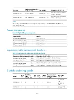
S12518-AC 12240 W
11025 W
•
Net weight:
166.8 kg (367.72 lb)
•
Full configuration:
≤
315 kg (694.44 lb)
1686
×
442
×
740 mm (66.38
×
17.40
×
29.13 in)
38 RU
S12518-DC 12380 W
11025 W
•
Net weight:
170.8 kg (376.54 lb)
•
Full configuration:
≤
315 kg (694.44 lb)
1686
×
442
×
740 mm (66.38
×
17.40
×
29.13 in)
38 RU
Max system input power consumption refers to the maximum input power consumption of the chassis
when the chassis is fully configured with cards that have the maximum power consumption.
Max power consumption for cards and fans refers to the maximum power consumption of all cards and
fans that have the maximum power consumption in the fully configured chassis. For example, the max
power consumption of cards and fans for the S12508 is the maximum power consumption of eight
LST1XP16LEC1 cards, two LST1MRPNC1 MPUs, nine LST2SF08C1 switching fabric modules, and two
fan trays.
Net weight refers to the weight of the chassis (with filler panels installed), excluding fan trays, cards, and
power supplies.
Full configuration refers to the maximum weight of the switch when all cards and power supplies are
installed to the switch.
Rack Unit (RU) refers to the height of the chassis in the rack. 1 RU = 44.45 mm/1.75 in.
Cards
Table 33
Card specifications
LPU model
Power consumption
Net weight
Dimensions (H
×
W
×
D)
LST1MRPNC1
45 W to 70 W
3.85 kg (8.49 lb)
40 × 400 × 467 mm (1.57 ×
15.75 × 18.39 in)
LST1SF08B1
36 W to 45 W
1.37 kg (3.02 lb)
40 × 318 × 167 mm (1.57 ×
12.52 × 6.57 in)
LST1SF18B1
93 W to 110 W
2.68 kg (5.91 lb)
40 × 618 × 167 mm (1.57 ×
24.33 × 6.57 in)
LST2SF08C1
38 W to 50 W
1.35 kg (2.98 lb)
40 × 318 × 167 mm (1.57 ×
12.52 × 6.57 in)
LST2SF18C1
105 W to 125 W
2.65 kg (5.84 lb)
40 × 618 × 167 mm (1.57 ×
24.33 × 6.57 in)
LST1XP4LEB1
103 W to 135 W
4.33 kg (9.55 lb)
40 × 400 × 467 mm (1.57 ×
15.75 × 18.39 in)
LST1XP4LEC1
115 W to 150 W
4.46 kg (9.83 lb)
40 × 400 × 467 mm (1.57 ×
15.75 × 18.39 in)
Summary of Contents for S12500 Series
Page 40: ...30 Figure 28 Installing an upper expansion cable management bracket 1 2 3 4 5 6 7...
Page 109: ...99 Figure 74 Replacing a card for the S12504 A Card to be removed B Card to be installed...
Page 149: ...139 Figure 85 Loopback operation on an optical transceiver...
Page 164: ...154 Figure 100 Example of a device label...

