8
•
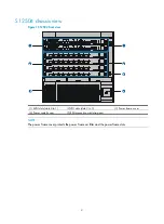
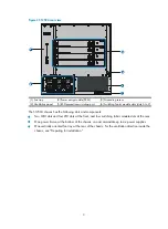
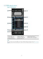
Two MPU slots and 18 LPU slots at the front, and nine switching fabric module slots at the rear.
•
Two power frames at the top, and each power frame can accommodate up to six power supplies.
•
Two horizontally oriented fan trays at the rear. For the ventilation direction inside the chassis, see
"Preparing for installation."
Backplane
The backplane of an S12500 switch is located inside the chassis. It provides high-speed data switching
between switching fabric modules and LPUs, and exchanges management and control signals between
MPUs and LPUs/switching fabric modules. The backplane provides the following capabilities:
•
Provides communication channels for signal exchange between cards.
•
Supports hot-swapping of cards.
•
Identifies card type.
•
Connects to the power frame, provides distributed power for MPUs, LPUs, switching fabric modules,
fan trays and power supplies, and provides monitoring channels for MPUs to monitor power frame
status.
Fan tray
A fan tray contains fan units. The dimension of each fan unit is 120 × 120 × 38 mm (4.72 × 4.72 ×1.50
in).
An S12504 uses one fan tray, which comprises eight fan units and one fan monitoring board.
An S12508 or S12518 uses an upper fan tray at the top and a lower fan tray at the bottom. Each fan tray
comprises 12 fan units and one fan monitoring board.
S12500 fan trays provide the following functions:
•
Effective heat dissipation and single-point of failure protection.
•
Status monitoring, including fan rotation speed monitoring and fault alarming.
•
Fan speed can be controlled by the MPU or automatically adjusted based on temperature. An
S12504 has two groups of fans. An S12508 or S12518 has four groups of fans. Speed adjustment
is done on a per-group basis to decrease noise and improve energy efficiency.
•
Each fan tray has two LEDs on the front panel to show its operating status.
•
Hot swappable. The fans receive DC power from the backplane.
IMPORTANT:
The S12504, S12508, and S12518 use different fan trays, which cannot be replaced by one another.
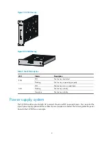
shows the S12504 fan tray, and
shows the S12508 fan tray. The S12508 fan tray and
S12518 fan tray look similar.
Summary of Contents for S12500 Series
Page 40: ...30 Figure 28 Installing an upper expansion cable management bracket 1 2 3 4 5 6 7...
Page 109: ...99 Figure 74 Replacing a card for the S12504 A Card to be removed B Card to be installed...
Page 149: ...139 Figure 85 Loopback operation on an optical transceiver...
Page 164: ...154 Figure 100 Example of a device label...

