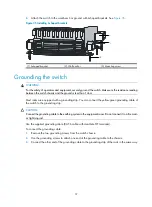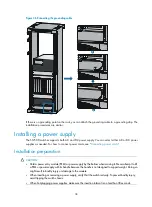
24
NOTE:
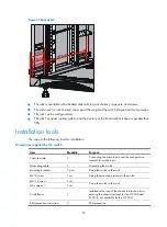
The number of screws and nuts supplied with the switch depends on those shipped from the factory.
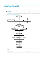
User-supplied tools and equipment
•
Mechanical lift
•
Phillips screwdriver P1 – 100 mm, P2 – 150 mm, and P3 – 250 mm
•
Flat screwdriver P4 – 75 mm
•
Marker
•
Tape
•
Diagonal pliers, wire-stripping pliers, and wire clippers
•
Socket wrench
•
Cables such as network cables and fiber cables
•
Meters and equipment, such as hub and multimeter
•
Configuration terminal, such as PC
NOTE:
The rack accessories and installation tools are not included in this section. The accessories and installation
tools may vary depending on the rack model. For more information, see the installation guide of the
corresponding rack.
Summary of Contents for S12500 Series
Page 40: ...30 Figure 28 Installing an upper expansion cable management bracket 1 2 3 4 5 6 7...
Page 109: ...99 Figure 74 Replacing a card for the S12504 A Card to be removed B Card to be installed...
Page 149: ...139 Figure 85 Loopback operation on an optical transceiver...
Page 164: ...154 Figure 100 Example of a device label...

