38
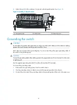
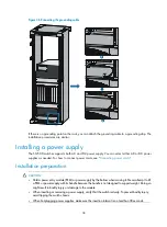
Figure 36
Connecting the grounding cable
If there is no grounding point on the rack, you can attach the grounding cable to a grounding strip. The
installation procedures are similar.
Installing a power supply
The S12500 switches supports both AC and DC power supply. You can select either AC or DC power
supplies as needed. For how to connect power cords, see "
Installation preparation
CAUTION:
•
Hold a power entry module (PEM) or power supply by the bottom when moving it. Never attempt to lift
a PEM or power supply with its handle because the handle is not designed to support weight. Doing so
might result in bodily injury or damage to the module.
•
When inserting or removing a power supply, verify that the switch is sturdy. To prevent bodily injury,
avoid tipping the switch chassis.
•
When hot-plugging power supplies, make sure the insertion interval is no less than 30 seconds.
Summary of Contents for S12500 Series
Page 40: ...30 Figure 28 Installing an upper expansion cable management bracket 1 2 3 4 5 6 7...
Page 109: ...99 Figure 74 Replacing a card for the S12504 A Card to be removed B Card to be installed...
Page 149: ...139 Figure 85 Loopback operation on an optical transceiver...
Page 164: ...154 Figure 100 Example of a device label...


