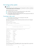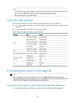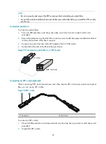
44
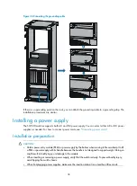
Figure 42
Removing the protective box
4.
Move the ejector levers on the front panel of the MPU outwards, hold up the MPU by one hand
without touching any electronic components on the MPU, and hold the front panel by the other
hand to push the MPU into the slot along the slide rails slowly.
5.
Push the ejector levers inward to ensure close contact between the MPU and the backplane.
6.
Position the screws into the holes and fasten them with a screwdriver to attach the MPU.
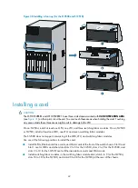
Figure 43
Installing an MPU (for the S12504)
Summary of Contents for S12500 Series
Page 40: ...30 Figure 28 Installing an upper expansion cable management bracket 1 2 3 4 5 6 7...
Page 109: ...99 Figure 74 Replacing a card for the S12504 A Card to be removed B Card to be installed...
Page 149: ...139 Figure 85 Loopback operation on an optical transceiver...
Page 164: ...154 Figure 100 Example of a device label...


