51
1.
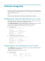
Connect the DB-9 connector of the console cable to the serial port of a PC or terminal.
2.
Connect the RJ-45 connector of the console cable to the console port of the MPU of the switch.
NOTE:
•
If two MPUs are installed on the switch, log in through the console port on the active MPU (typically with
a smaller slot number) for the first login.
•
When you remove the console cable, first unplug the RJ-45 end, and then the DB-9 end.
Setting up a configuration environment
1.
Select
Start
>
All Programs
>
Accessories
>
Communications
>
HyperTerminal
.
The
Connection Description
dialog box appears.
2.
Enter the name of the new connection in the
Name
field and click
OK
.
NOTE:
If you use the Windows 2003 Server operating system on your PC, add a HyperTerminal, and then log in
to and manage the switch as described in this document. If you use Windows 2008 Server, Windows 7,
Windows Vista, or any other operating system on your PC, use the third party terminal software. For how
to use the third party terminal software, see the user guide or online help of that software.
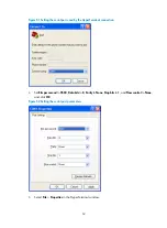
Figure 50
Connection description
3.
Select the serial port to be used from the
Connect using
list, and click
OK
.
Summary of Contents for S12500 Series
Page 40: ...30 Figure 28 Installing an upper expansion cable management bracket 1 2 3 4 5 6 7...
Page 109: ...99 Figure 74 Replacing a card for the S12504 A Card to be removed B Card to be installed...
Page 149: ...139 Figure 85 Loopback operation on an optical transceiver...
Page 164: ...154 Figure 100 Example of a device label...


