46
2.
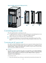
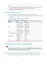
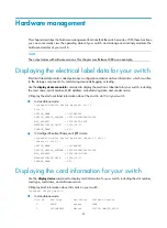
Insert the connector of the AC power cord into the PEM receptacle.
3.
Install the retention clip to the connector and fasten the screws to lock the power connector.
4.
Connect the other end of the AC power cord to the power source.
Figure 45
Connecting the AC power cord
Connecting a DC power cord
Six pairs of wiring terminals (marked PSR1 through PSR6) are available on the DC grounding strip of the
S12500 switches. The wiring terminals correspond to the power supplies 1 through 6, respectively. The
power source supplies power to the switch through the wiring terminals. If slot 1 is installed with a power
supply, the wiring terminals marked PSR1 must be connected to the power source with a DC power cord
to make the power supply operate properly.
CAUTION:
A plastic protection cover is installed in front of the grounding strip to protect operators from being
shocked. Remove the protection cover before connecting power cords and then install the protection cover
in time.
To connect a DC power cord:
1.
Remove the protection cover from the power supply.
Summary of Contents for S12500 Series
Page 40: ...30 Figure 28 Installing an upper expansion cable management bracket 1 2 3 4 5 6 7...
Page 109: ...99 Figure 74 Replacing a card for the S12504 A Card to be removed B Card to be installed...
Page 149: ...139 Figure 85 Loopback operation on an optical transceiver...
Page 164: ...154 Figure 100 Example of a device label...


