background image

15 


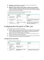
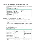
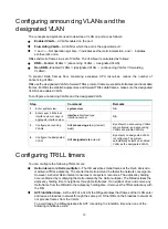
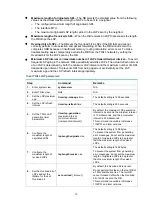
Maximum length of originated LSPs

—The RB selects the smallest value from the following 

values as the actual maximum length of LSPs to be sent to a neighbor: 

{


The configured maximum length of originated LSPs.  

{


The interface MTU.  

{


The maximum originated LSP length carried in the LSPs sent by the neighbor.  


Maximum length of received LSPs

—When the RB receives an LSP that exceeds the length, 

the RB drops the LSP.  


Overload bit of LSPs

—The RB sets the Overload bit in LSPs if the RB fails and cannot 

correctly perform route selection and packet forwarding. When the RB cannot record the 
complete LSDB because of insufficient memory, routing calculation errors occur. To make 
troubleshooting easier, temporarily exclude the RB from the TRILL network by setting the 
Overload bit for the LSPs sent by the RB.  


Minimum LSP interval

 and 

maximum number of LSPs transmitted per interval

—To avoid 

frequent LSP aging in the network, RBs periodically advertise LSPs. The actual refresh interval 
of an LSP is determined by both the minimum LSP interval and the maximum number of LSPs 
transmitted per interval. To prevent LSPs from being aged out accidentally, set the LSP 
maximum age and the LSP refresh interval appropriately.  

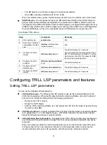
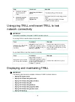
To set TRILL LSP parameters: 


Step Command


Remarks


1. 

Enter system view. 


system-view 

N/A 

2. 

Enter TRILL view.  

trill

 N/A 

3. 

Set the LSP maximum 
age.  

timer


lsp-max-age


time 

The default setting is 1200 seconds.  

4. 

Set the LSP refresh 
interval.  

timer


lsp-refresh


time 

The default setting is 900 seconds.  

5. 

Set the TRILL LSP 
generation timer 
parameters. 

timer


lsp-generation


maximum-interval


minimum-interval


incremental-interval

 ] ]


By default, the maximum LSP generation 
interval is 2 seconds, the minimum interval 
is 10 milliseconds, and the incremental 
interval is 20 milliseconds. 
This command is available in Release 
1138P01 and later versions. 

6. 

Configure the 
maximum length of 
originated LSPs. 

lsp-length


originate


size 

The default setting is 1458 bytes.  
To prevent the system from generating 
error messages, do not set the maximum 
length of originated LSPs to be greater 
than the maximum length of received 
LSPs.  

7. 

Configure the 
maximum length of 
received LSPs. 

lsp-length


receive


size 

The default setting is 1492 bytes.  
To prevent the system from generating 
error messages, do not set the maximum 
length of originated LSPs to be greater 
than the maximum length of received 
LSPs. 

8. 

Set the Overload bit of 
LSPs and set the 
lifetime for the set 
Overload bit. 

set overload

 [ 

timeout

 ]


By default, the Overload bit is not set.  
Do not perform this task on the root RB of 
a TRILL distribution tree. The root RB 
cannot forward traffic when the Overload 
bit of LSPs is set on the RB. 
This command is available in Release 
1138P01 and later versions. 

Summary of Contents for S12500-X

Page 1: ...H3C S12500 X S12500X AF Switch Series TRILL Configuration Guide Hangzhou H3C Technologies Co Ltd http www h3c com Software version Release 1135 and later Document version 6W101 20151130...

Page 2: ...ne SecPath SecCenter SecBlade Comware ITCMM and HUASAN are trademarks of Hangzhou H3C Technologies Co Ltd All other trademarks that may be mentioned in this manual are the property of their respective...

Page 3: ...ribes the conventions used in this documentation set Command conventions Convention Description Boldface Bold text represents commands and keywords that you enter literally as shown Italic Italic text...

Page 4: ...alert that provides helpful information Network topology icons Represents a generic network device such as a router switch or firewall Represents a routing capable device such as a router or Layer 3 s...

Page 5: ...ware installation software upgrading and software feature configuration and maintenance documentation Products Solutions Provides information about products and technologies as well as solutions Techn...

Page 6: ...t advertisement 16 Enabling TRILL pseudonode bypass 16 Setting the SPF algorithm parameters 17 Configuring TRILL distribution trees 17 Setting basic distribution tree parameters 17 Enabling TRILL dist...

Page 7: ...k The nickname is 2 bytes in length Link State Database The LSDB contains all link state information in the TRILL network Link State Protocol Data Unit An LSP describes local link state information an...

Page 8: ...multicast broadcast or unknown unicast frame Op Length Length of the Options field 0 indicates that the Options field does not exist Hop Count Hop count which is used to avoid loops An RB drops a TRI...

Page 9: ...on receiving the TRILL frame the egress RB de encapsulates it to obtain the original Ethernet frame and sends the frame to the target device Figure 2 Layer 2 unicast frame forwarding flow The outer Et...

Page 10: ...links exist in the network each TRILL distribution tree selects the link with the largest pseudonode ID for forwarding packets As shown in Figure 4 two equal cost links exist between RB 1 and RB 2 As...

Page 11: ...B 2 is assigned to the TRILL distribution tree rooted at RB 4 TRILL distribution trees support fast root switching When an RB detects that the root of a distribution tree is unreachable the RB deletes...

Page 12: ...ble in Release 1138P01 and later versions You can use ping TRILL and tracert TRILL to test TRILL network connectivity when network failure occurs or new RBs are added to the network Ping TRILL and tra...

Page 13: ...ication to the source RB because the hop count of the request is 0 The notification uses the nickname of RB 2 as the ingress RB In this way RB 1 can get the nickname of the first hop RB 3 RB 1 sends R...

Page 14: ...ance OAM Support Configuration restrictions and guidelines When you configure TRILL follow these restrictions and guidelines Configuration in Layer 2 Ethernet interface view takes effect only on the c...

Page 15: ...DRB priority of a TRILL port Optional Setting the link cost for a TRILL port Optional Configuring announcing VLANs and the designated VLAN Optional Configuring TRILL timers Optional Configuring TRILL...

Page 16: ...ure 9 Two TRILL neighbors are established for a port 2 After you enable TRILL on a port TRILL can operate correctly by using default settings A port with TRILL enabled is called a TRILL port To enable...

Page 17: ...cknames to RBs and the priority for a RB to hold a nickname is 64 Configuring the link type of a TRILL port The following link types are available for a TRILL port Access Access ports include access p...

Page 18: ...If no link cost is set and automatic link cost calculation is enabled the calculated link cost takes effect If no link cost is set and automatic link cost calculation is disabled the default link cost...

Page 19: ...figure announcing VLANs trill announcing vlan vlan list null By default no announcing VLANs are configured and announcing VLANs are enabled VLANs 4 Configure the designated VLAN trill designated vlan...

Page 20: ...is 3 5 Configure the AVF inhibition time trill timer avf inhibited time The default setting is 30 seconds 6 Configure the CSNP interval trill timer csnp interval The default setting is 10 seconds Conf...

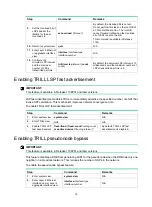
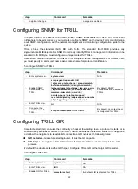
Page 21: ...er system view system view N A 2 Enter TRILL view trill N A 3 Set the LSP maximum age timer lsp max age time The default setting is 1200 seconds 4 Set the LSP refresh interval timer lsp refresh time T...

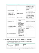
Page 22: ...le in Release 1138P01 and later versions LSP fast advertisement enables TRILL to immediately advertise the specified number of LSPs that invoke SPF calculation This mechanism improves network converge...

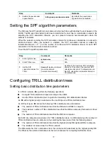
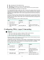
Page 23: ...he minimum SPF calculation interval is 10 milliseconds and the SPF calculation incremental interval is 20 milliseconds Configuring TRILL distribution trees Setting basic distribution tree parameters I...

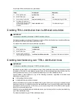
Page 24: ...load balancing over TRILL distribution trees IMPORTANT This feature is available in Release 1138P01 and later versions By default ingress traffic is not load balanced over TRILL distribution trees af...

Page 25: ...distribution trees do not use equal cost routes to share traffic When multicast ECMP is enabled TRILL assigns equal cost routes to multiple TRILL distribution trees to improve load sharing performanc...

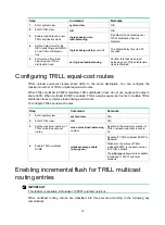
Page 26: ...iew trill N A 3 Enable incremental flush for TRILL multicast routing entries flush policy difference By default incremental flush is disabled for TRILL multicast routing entries Configuring TRILL Laye...

Page 27: ...t the interface is an access port 9 Assign the interface to the VLANs enabled with Layer 3 forwarding and the designated VLAN Assign the trunk port to the specified VLANs port trunk permit vlan vlan i...

Page 28: ...mismatch buffsize mismatch id length mismatch lsdboverload state change lsp parse error lsp size exceeded max seq exceeded maxarea mismatch new drb own lsp purge protocol support rejected adjacency sk...

Page 29: ...terval priority priority t timeout nickname Execute this command in any view If multiple routes destined for the RB exist the RB is reachable if any of the routes is reachable To use tracert TRILL to...

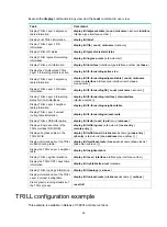
Page 30: ...rface interface number Display TRILL Layer 3 neighbor table information display trill l3 forwarding neighbor table Display TRILL Layer 3 unicast routing table information display trill l3 forwarding u...

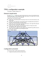
Page 31: ...orwarding on RB 1 Specify VLAN interface 100 s IP address 100 1 1 1 as the gateway of the users in VLAN 100 and VLAN interface 200 s IP address 200 1 1 1 as the gateway of the users in VLAN 200 Figure...

Page 32: ...o VLAN 1000 and assign the ports to VLAN 100 and VLAN 1000 RB3 if range port link type trunk RB3 if range port trunk pvid vlan 1000 RB3 if range port trunk permit vlan 100 1000 RB3 if range quit Confi...

Page 33: ...AN 100 and VLAN 200 RB1 trill RB1 trill l3 forwarding enable RB1 trill l3 forwarding vlan 100 200 RB1 trill quit Create VLAN interface 100 and assign IP address 100 1 1 1 24 to the VLAN interface RB1...

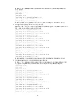
Page 34: ...x5801 XGE1 0 3 0x5802 0x5806 XGE1 0 2 0x5801 XGE1 0 3 0x5802 Display TRILL Layer 3 unicast routing table information on RB 1 RB1 display trill l3 forwarding unicast route Destinations 6 Unicast routes...

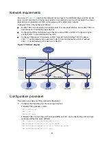
Page 35: ...configure these uplink ports as trunk ports to pass TRILL frames to the TRILL network Enable TRILL on the downlink ports of distribution layer devices and configure these downlink ports as trunk port...

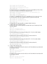
Page 36: ...RB1 Ten GigabitEthernet1 0 4 trill link type trunk RB1 Ten GigabitEthernet1 0 4 quit RB1 interface ten gigabitethernet 1 0 5 RB1 Ten GigabitEthernet1 0 5 trill enable RB1 Ten GigabitEthernet1 0 5 tril...

Page 37: ...stribution trees Set the RB 6 s priority to 65535 and set the number of TRILL distribution trees that the RB wants all RBs to compute to 4 RB6 trill RB6 trill tree root priority 65535 RB6 trill trees...

Page 38: ...3 0x5807 XGE1 0 4 0x5808 XGE1 0 5 0x5809 0x5806 XGE1 0 2 Direct 0x5807 XGE1 0 3 Direct 0x5808 XGE1 0 4 Direct 0x5809 XGE1 0 5 Direct Use display trill multicast route to display the TRILL multicast r...

Page 39: ...ignated routing bridge 1 displaying TRILL 23 distributing TRILL distribution tree 17 TRILL distribution tree load balancing 18 TRILL distribution tree multithread calculation 18 TRILL distribution tre...

Page 40: ...eighbor TRILL neighbor change logging 21 network Layer 2 TRILL forwarding mechanisms 3 Layer 3 TRILL forwarding mechanisms 5 ping TRILL connectivity test 23 pseudonode bypass 16 tracert TRILL node fai...

Page 41: ...configuring TRILL RB system ID 10 configuring TRILL SNMP 22 configuring TRILL timers 13 displaying TRILL 23 enabling TRILL 9 enabling TRILL distribution tree load balancing 18 enabling TRILL distribut...

Page 42: ...ribution tree parameter set 17 enable 9 equal cost route configuration 19 forwarding mechanisms 3 frame formats 1 GR configuration 22 how it works 2 Layer 2 forwarding mechanisms 3 Layer 3 forwarding...

Reviews: