6-3
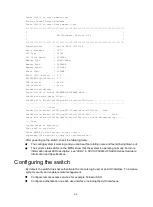
Press Ctrl+T to start memory test
Booting Normal Extend Bootware
Press Ctrl+V to start heavy memory test
****************************************************************************
* *
* MPU BootWare, Version 3.02 *
* *
****************************************************************************
Compiled Date : Apr 28 2019 10:27:24
Basic BootWare : 0107
CPU Type : C2538
CPU Clock Speed : 2400MHz
Memory Type : DDR3 SDRAM
Memory Size : 16384MB
Memory Speed : 1333MHz
Flash Size : 3630MB
BASIC CPLD Version : 2.0
EXTENDED CPLD Version : 2.0
PCB Version1 : Ver.A
PCB Version2 : Ver.A
BootWare Validating...
Press Ctrl+B to access EXTENDED-BOOTWARE MENU...
Loading the main image files...
Loading file flash:/s12500g-cmw710-system-e7593.bin.........................
............................................................................
..................Done.
Loading file flash:/s12500g-cmw710-freeradius-e7593.bin....Done.
Loading file flash:/s12500g-cmw710-boot-e7593.bin.................Done.
Image file flash:/s12500g-cmw710-boot-e7593.bin is self-decompressing.......
....Done.
System image is starting...
Line aux0 is available.
Press ENTER to get started. (Press Enter.)
<sysname> (The switch is ready for configuration.)
After powering on the switch, check the following items:
•
The cooling system is working, and you can hear fan rotating noise and feel air being blown out.
•
The system status LEDs on the MPUs show that the system is operating normally. For more
information about LED description, see "LEDs" in
H3C S12500G-AF Switch Series Hardware
Information and Specifications
.
Configuring the switch
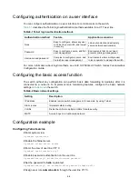
By default, the switch does not authenticate the console login user at an AUX interface. To increase
system security and enable remote management:
•
Configure remote access services, for example, Telnet or SSH.
•
Configure authentication on each user interface, including the AUX interfaces.
Summary of Contents for S12500G-AF Series
Page 32: ...3 15 Figure3 16 Connecting the grounding cable to a grounding strip 1 2 4 3 6 5 ...
Page 49: ...4 16 Figure4 16 Connecting an SFP DAC cable 1 Pull latch 2 Connector 1 2 ...
Page 92: ...A 12 FigureA 14 Example of a device label ...
Page 104: ...C 6 FigureC 5 Securing the chassis to the pallet base S12504G AF switch 1 1 2 2 1 ...

