B-1
Appendix B Cabling recommendations
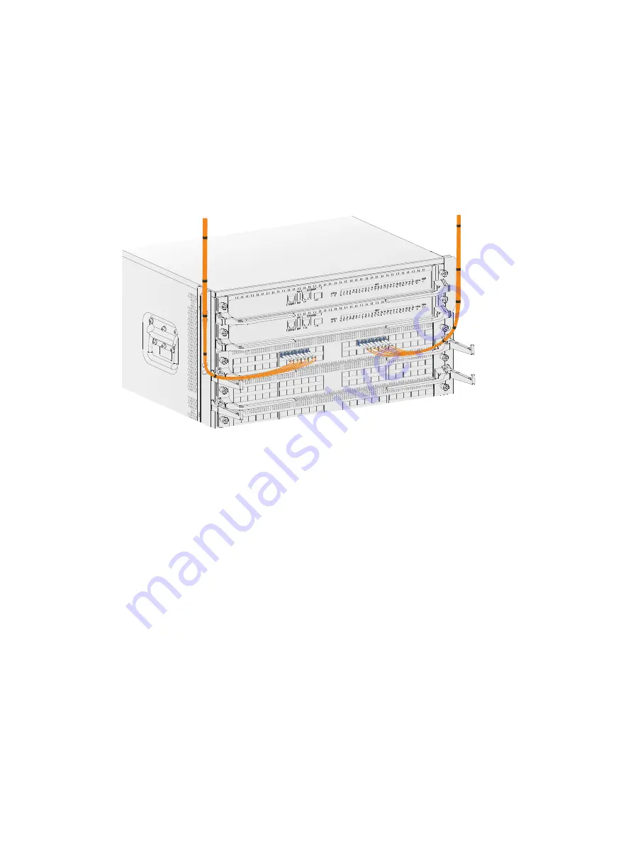
Routing signal cables
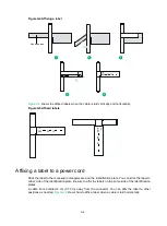
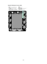
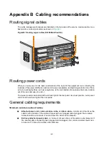
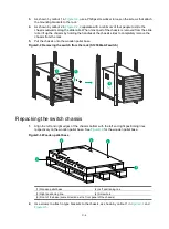
The cable management brackets are installed on the two sides of the service module section. As a
best practice, route signal cables as shown in
FigureB-1 Routing signal cables (S12508G-AF switch)
Routing power cords
When you route power cords, take consideration of the layout of the equipment room, including the
locations of the power distribution cabinet, AC power receptacles, and lightning protection box. Place
all re-connecting facilities, such as receptacles, at the rack bottom (Do not place them at a location
out of the rack and easy to reach.)
The power modules are located at the left and right of the rear panel. As a best practice, route power
cords from the left and right of the rear panel.
General cabling requirements
Minimum curvature radius of cables
•
Attached power cord, communication cable, or ribbon cable
—A minimum of five times the
cable's outer diameter. If the cable is frequently bent, plugged and unplugged, the curvature
radius should be a minimum of seven times the cable's outer diameter.
•
Ordinary attached coaxial cable
—A minimum of seven times of the cable's outer diameter. If
the coaxial cable is frequently bent, plugged and unplugged, the curvature radius should be a
minimum of 10 times the cable's outer diameter.
Summary of Contents for S12500G-AF Series
Page 32: ...3 15 Figure3 16 Connecting the grounding cable to a grounding strip 1 2 4 3 6 5 ...
Page 49: ...4 16 Figure4 16 Connecting an SFP DAC cable 1 Pull latch 2 Connector 1 2 ...
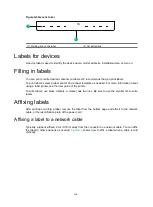
Page 92: ...A 12 FigureA 14 Example of a device label ...
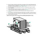
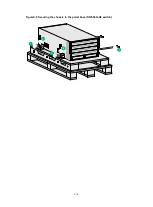
Page 104: ...C 6 FigureC 5 Securing the chassis to the pallet base S12504G AF switch 1 1 2 2 1 ...

