7-4
MPU failure
Symptom
The LED for the MPU is steady red or flashing red.
Solution
To resolve the issue:
1.
Verify that the power system is operating correctly. For more information, see "
."
2.
Remove and reinstall the MPU to make sure it is installed securely. For more information, see
"Installing MPUs and service modules."
3.
Press the
RESET
button on the MPU to reset the MPU. After the MPU is reset, verify that the
LED for the MPU is flashing green.
4.
If the switch has empty MPU slots, install the MPU in the empty MPU slot, and verify that the
MPU can operate correctly.
5.
If the issue persists, contact H3C Support.
NOTE:
•
On the S12516G-AF and S12508G-AF, the MPU and service module slot numbers are marked
on the ejector lever pillow blocks at the left and right sides of the slots. The fabric module slot
number is marked above the slot.
•
On the S12504G-AF, the MPU slot number is marked at the left side of the slot. The service
module slot number is marked on the ejector lever pillow blocks at the left and right sides of the
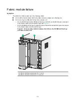
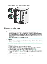
slot. You can see the fabric module slot numbers through the openings in the fan trays, as shown
by callout 3 in the
Service module failure
Symptom
The LED for the service module is steady red or flashing red.
Solution
To resolve the issue:
1.
Verify that the MPU is operating correctly. For more information, see "
."
2.
Verify that the system software is compatible with the service module. Upgrade the system
software if it is not compatible with the service module.
3.
Calculate the total power consumption, and make sure your power modules can provide
enough power. For more information, see
H3C S12500G-AF Switch Series Hardware
Information and Specifications
.
4.
Remove and reinstall the service module to make sure it is installed securely. For more
information about installing a service module, see "Installing MPUs and service modules."
5.
If the switch has empty service module slots, install the module in an empty service module slot.
If the service module operates correctly, the previous slot is faulty.
6.
If the issue persists, contact H3C Support.
Summary of Contents for S12500G-AF Series
Page 32: ...3 15 Figure3 16 Connecting the grounding cable to a grounding strip 1 2 4 3 6 5 ...
Page 49: ...4 16 Figure4 16 Connecting an SFP DAC cable 1 Pull latch 2 Connector 1 2 ...
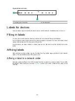
Page 92: ...A 12 FigureA 14 Example of a device label ...
Page 104: ...C 6 FigureC 5 Securing the chassis to the pallet base S12504G AF switch 1 1 2 2 1 ...

