17
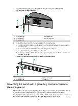
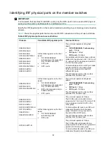
Weld the yellow-green grounding cable to the angel iron or steel tube and treat the joint for corrosion
protection.
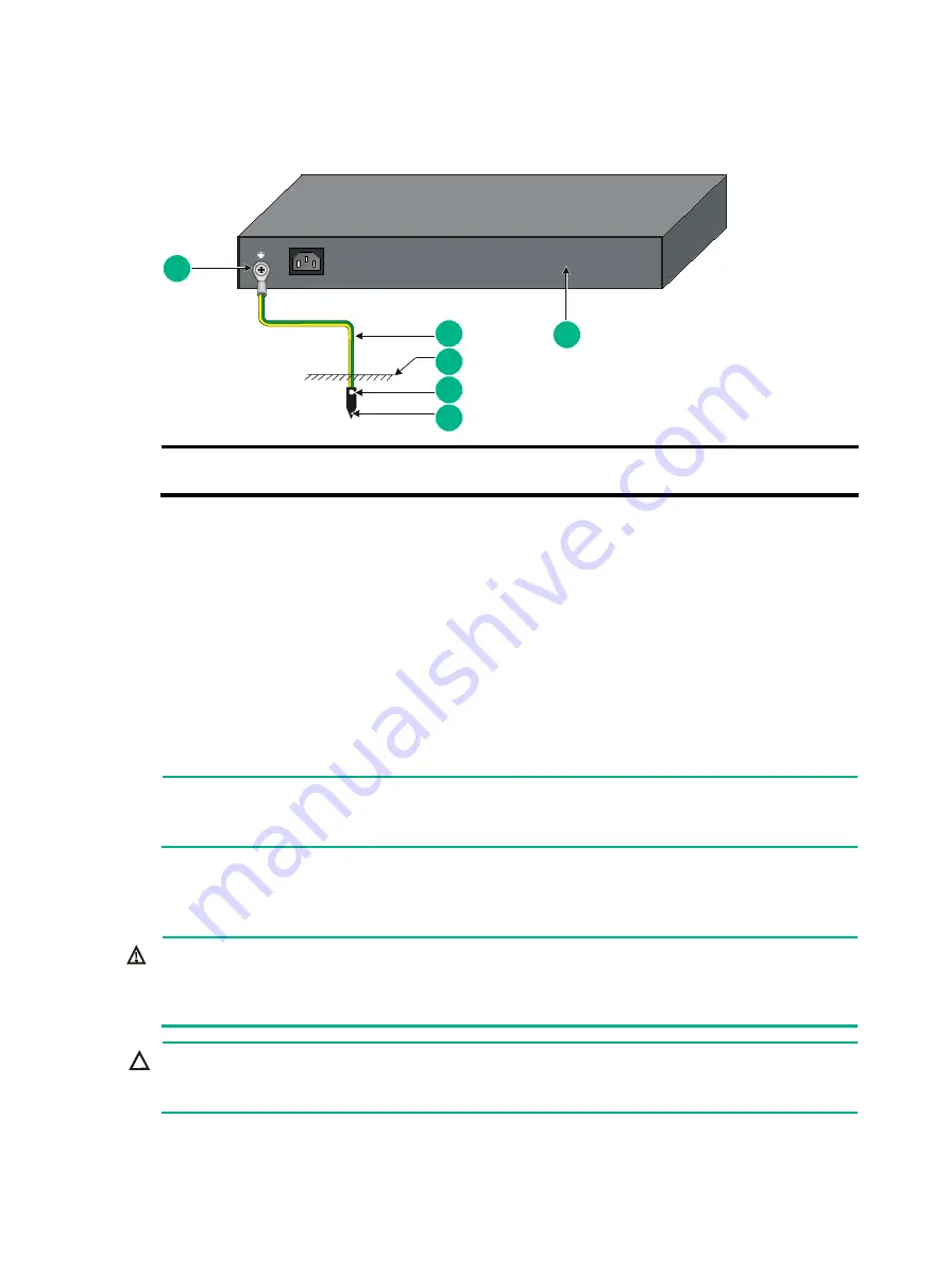
Figure 19 Grounding the switch by burying the grounding conductor into the earth ground
(1) Grounding screw
(2) Grounding cable
(3) Earth
(4) Joint
(5) Grounding conductor
(6) Chassis rear panel
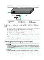
Grounding the switch by using the PE wire of the AC power
cord
If the installation site has no grounding strips or earth ground, ground an AC-powered switch through
the PE wire of the power cord. Make sure the following requirements are met:
•
The power cord has a PE wire.
•
The ground contact in the power outlet is securely connected to the ground in the power
distribution room or on the AC transformer side.
•
The power cord is securely connected to the power outlet. If the ground contact in the power
outlet is not connected to the ground, report the problem and reconstruct the grounding system.
NOTE:
To guarantee the grounding effect, use the grounding cable provided with the switch to connect to
the grounding strip in the equipment room.
Installing and removing a power module
WARNING!
In power redundancy mode, you can replace a power module without powering off the switch but
must follow the installation and procedures in
and
damage to the switch.
CAUTION:
Provide a circuit breaker for each power module and make sure the circuit breaker is off before
installation.
The S5560S-28F-SI, S5560S-28DP-SI, and S5130S-28F-SI switches each provide two power
module slots and come with power module slot 1 installed with a PSR75-12A power module and
1
2
5
4
3
6

