44
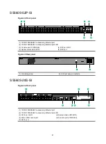
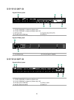
S5560S-28DP-SI
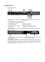
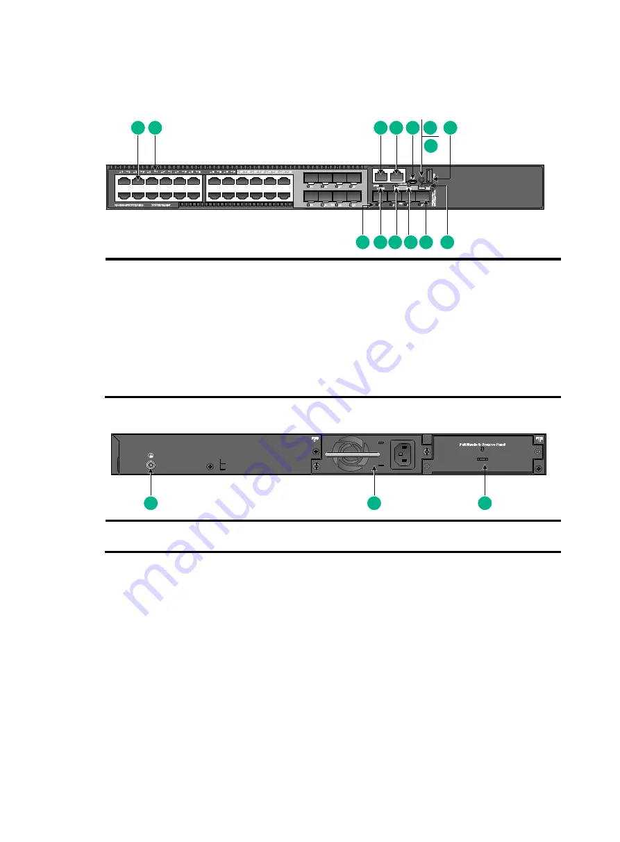
Figure 50 Front panel
(1) 10/100/1000BASE-T autosensing Ethernet port
(2) 10/100/1000BASE-T autosensing Ethernet port LED
(3) Management Ethernet port
(4) Console port (CONSOLE)
(5) Micro USB console port
(6) Mode button
(7) Mode LED (MODE)
(8) USB port
(9) System status LED (SYS)
(10) SFP port
(11) Power module 2 status LED (PWR2)
(12) Power module 1 status LED (PWR1)
(13) Management Ethernet port LED (ACT/LINK)
(14) SFP port LED
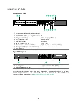
Figure 51 Rear panel
(1) Grounding screw
(2) Power module slot 1 (PWR1)
(3) Power module slot 2 (PWR2)
An S5560S-28DP-SI switch comes with power module slot 1 installed with a PSR75-12A power
module and power module slot 2 installed with a filler panel. For information about installing and
removing a power module, see "
Installing and removing a power module
1
2
3
5
4
6
7
8
9
10
11
12
13
14
1
2
3

