background image


Preparing for installation 

This document provides an installation guide for the following switch series: 


S5560S-SI switch series 


S5130S-SI switch series 


S5130S-LI switch series 


S5120V2-SI switch series 


S5120V2-LI switch series 


S5110V2-SI switch series 


S5000V3-EI switch series 


S5500V3-SI switch series 


S3100V3-SI switch series 

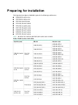
Table 1 

describes the switch models that each switch series includes. 

Table 1 Switch series and models 

Switch series 

Model 

Product code 

S5560S-SI switch 
series 

Non-PoE 
models 

S5560S-28P-SI 

LS-5560S-28P-SI 

LS-5560S-28P-SI-GL 

S5560S-52P-SI 

LS-5560S-52P-SI 

LS-5560S-52P-SI-GL 

S5560S-28S-SI 

LS-5560S-28S-SI 

LS-5560S-28S-SI-GL 

S5560S-52S-SI 

LS-5560S-52S-SI 

LS-5560S-52S-SI-GL 

S5560S-28F-SI 

LS-5560S-28F-SI 

S5560S-28DP-SI 

LS-5560S-28DP-SI 

S5130S-SI switch 
series 

Non-PoE 
models 

S5130S-28S-SI 

LS-5130S-28S-SI 

S5130S-52S-SI 

LS-5130S-52S-SI 

S5130S-28F-SI 

LS-5130S-28F-SI 

S5130S-LI switch 
series 

Non-PoE 
models 

S5130S-28S-LI 

LS-5130S-28S-LI 

LS-5130S-28S-LI-GL 

S5130S-52S-LI 

LS-5130S-52S-LI 

LS-5130S-52S-LI-GL 

PoE models 

S5130S-28S-PWR-LI 

LS-5130S-28S-PWR-LI 

S5130S-28S-HPWR-LI 

LS-5130S-28S-HPWR-LI 

S5130S-52S-PWR-LI 

LS-5130S-52S-PWR-LI 

S5120V2-SI 
switch series 

Non-PoE 
models 

S5120V2-10P-SI 

LS-5120V2-10P-SI 

S5120V2-28P-SI 

LS-5120V2-28P-SI 

S5120V2-52P-SI 

LS-5120V2-52P-SI 

Summary of Contents for S3100V3-SI

Page 1: ...60S SI Switch Series H3C S5500V3 SI Switch Series H3C S5130S SI Switch Series H3C S5130S LI Switch Series H3C S5120V2 SI Switch Series H3C S5120V2 LI Switch Series H3C S5110V2 SI Switch Series H3C S5000V3 EI Switch Series H3C S3100V3 SI Switch Series New H3C Technologies Co Ltd http www h3c com Document version 6W104 20190731 ...

Page 2: ...r respective owners Notice The information in this document is subject to change without notice All contents in this document including statements information and recommendations are believed to be accurate but they are presented without warranty of any kind express or implied H3C shall not be liable for technical or editorial errors or omissions contained herein Environmental protection This prod...

Page 3: ...eplace with actual values Square brackets enclose syntax choices keywords or arguments that are optional x y Braces enclose a set of required syntax choices separated by vertical bars from which you select one x y Square brackets enclose a set of optional syntax choices separated by vertical bars from which you select one or none x y Asterisk marked braces enclose a set of required syntax choices ...

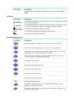
Page 4: ...ns Convention Description Represents a generic network device such as a router switch or firewall Represents a routing capable device such as a router or Layer 3 switch Represents a generic switch such as a Layer 2 or Layer 3 switch or a router that supports Layer 2 forwarding and other Layer 2 features Represents an access controller a unified wired WLAN module or the access controller engine on ...

Page 5: ...hardware model configuration or software version It is normal that the port numbers sample output screenshots and other information in the examples differ from what you have on your device Documentation feedback You can e mail your comments about product documentation to info h3c com We appreciate your comments ...

Page 6: ...power module 21 Connecting the power cord for a PSR75 12A power module 21 Verifying the installation 22 Accessing the switch for the first time 23 Managing the switch from the GUI 23 Accessing the GUI 23 Changing the default login password 23 Creating user accounts 23 Managing the switch from the CLI 24 Setting up the configuration environment 24 Starting the switch 27 Setting up an IRF fabric 29 ...

Page 7: ...I 52 S5120V2 28P HPWR LI 53 S5120V2 52P PWR LI 53 S5120V2 12TP HPWR LI 54 S5110V2 28P SI 55 S5110V2 52P SI 55 S5016PV3 EI 56 S5024PV3 EI 57 S5048PV3 EI 57 S5024PV3 EI PWR 58 S5024PV3 EI HPWR 59 S5048PV3 EI PWR 59 S5024FV3 EI 60 S5500V3 24P SI 61 S5500V3 48P SI 61 S3100V3 10TP SI 62 S3100V3 18TP SI 63 S3100V3 28TP SI 63 S3100V3 52TP SI 64 S3100V3 10TP PWR SI 65 S3100V3 20TP PWR SI 65 S3100V3 28TP P...

Page 8: ... port 86 Combo interface 88 LEDs 88 System status LED 88 Management Ethernet port LED 89 Power module status LED 89 RPS status LED 89 Mode LED MODE 89 SFP SFP port LED 90 10 100BASE T autosensing Ethernet port LED and 10 100 1000BASE T autosensing Ethernet port LED 90 ...

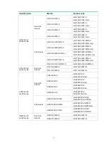
Page 9: ...P SI GL S5560S 52P SI LS 5560S 52P SI LS 5560S 52P SI GL S5560S 28S SI LS 5560S 28S SI LS 5560S 28S SI GL S5560S 52S SI LS 5560S 52S SI LS 5560S 52S SI GL S5560S 28F SI LS 5560S 28F SI S5560S 28DP SI LS 5560S 28DP SI S5130S SI switch series Non PoE models S5130S 28S SI LS 5130S 28S SI S5130S 52S SI LS 5130S 52S SI S5130S 28F SI LS 5130S 28F SI S5130S LI switch series Non PoE models S5130S 28S LI L...

Page 10: ...52P PWR LI LS 5120V2 52P PWR LI LS 5120V2 52P PWR LI GL S5120V2 12TP HPWR LI LS 5120V2 12TP HPWR LI S5110V2 SI switch series Non PoE models S5110V2 28P SI LS 5110V2 28P SI S5110V2 52P SI LS 5110V2 52P SI S5000V3 EI switch series Non PoE models S5016PV3 EI LS 5016PV3 EI LS 5016PV3 EI GL S5024PV3 EI LS 5024PV3 EI LS 5024PV3 EI GL S5048PV3 EI LS 5048PV3 EI LS 5048PV3 EI GL S5024FV3 EI LS 5024FV3 EI L...

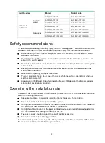
Page 11: ...ch free of obstruction Make sure the operating voltage is as required To avoid electrical shocks do not open the chassis while the switch is operating or when the switch is just powered off Always wear an ESD wrist strap when installing the switch Make sure the strap makes good skin contact and is reliably grounded Examining the installation site The switch must be used indoors You can mount your ...

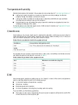
Page 12: ...e humidity is low In the worst case electrostatic adsorption can cause communication failure Table 2 Dust concentration limit in the equipment room Substance Concentration limit particles m Dust 3 x 10 4 no visible dust on the tabletop over three days NOTE Dust diameter 5 μm The equipment room must also meet strict limits on salts acids and sulfides to eliminate corrosion and premature aging of co...

Page 13: ...ent caused by lightning strikes only route interface cables indoors Laser safety WARNING Disconnected optical fibers or transceiver modules might emit invisible laser light Do not stare into beams or view directly with optical instruments when the switch is operating The switch is Class 1 laser device Installation tools No installation tools are provided with the switch Prepare them yourself as re...

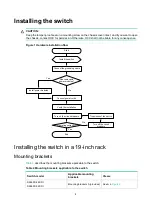
Page 14: ...ackets Table 4 describes the mounting brackets applicable to the switch Table 4 Mounting brackets applicable to the switch Switch model Applicable mounting brackets Views S5560S 28P SI S5560S 52P SI Mounting brackets A provided See A in Figure 2 Start Install the switch Connect the grounding cable Connect power cords Verify the installation Turn on the circuit breakers Operating correctly Turn off...

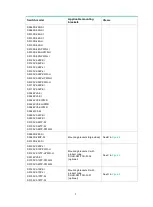
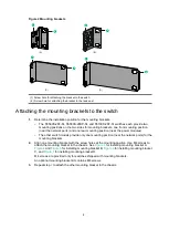
Page 15: ...024PV3 EI PWR S5024PV3 EI HPWR S5048PV3 EI PWR S5024FV3 EI S5500V3 24P SI S5500V3 48P SI S3100V3 28TP SI S3100V3 52TP SI S3100V3 28TP PWR SI S5560S 28F SI S5560S 28DP SI S5130S 28F SI Mounting brackets B provided See B in Figure 2 S5120V2 20P LI S5120V2 10P PWR LI S5120V2 12TP HPWR LI S5016PV3 EI S3100V3 10TP PWR SI S3100V3 20TP PWR SI Mounting brackets C with product code SOHO SWITCH FL 02 option...

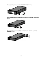
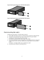
Page 16: ... the power modules The other switch models provide only one mounting position near the network ports for the mounting brackets 2 Align one mounting bracket with the screw holes at the mounting position Use M4 screws to attach the mounting bracket to the chassis See Figure 3 for installing mounting bracket A Figure 4 and Figure 5 for installing mounting bracket B Figure 6 for installing mounting br...

Page 17: ...acket A S5120V2 28P HPWR LI switch Figure 4 Attaching mounting bracket B mounting position near the port side S5560S 28F SI switch Figure 5 Attaching mounting bracket B mounting position near the power module side S5560S 28F SI switch ...

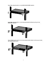
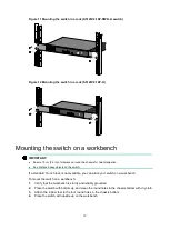
Page 18: ...at the mounting brackets have been securely attached to the switch chassis 3 Install cage nuts in the mounting holes in the rack posts No cage nuts are provided with the switch Prepare them yourself 4 One person holds the switch chassis and aligns the mounting brackets with the mounting holes in the rack posts and the other person attaches the mounting brackets to the rack with M6 screws If the sw...

Page 19: ...20V2 28P HPWR LI switch Figure 9 Mounting the switch in a rack mounting brackets installed near the port side S5560S 28F SI switch Figure 10 Mounting the switch in a rack mounting brackets installed near the power module side S5560S 28F SI switch ...

Page 20: ...n Do not place heavy objects on the switch If a standard 19 inch rack is not available you can place your switch on a workbench To mount the switch on a workbench 1 Verify that the workbench is sturdy and reliably grounded 2 Place the switch with bottom up and clean the round holes in the chassis bottom with dry cloth 3 Attach the rubber feet to the four round holes in the chassis bottom 4 Place t...

Page 21: ...ribes the switch models that support wall mounting and installation holes distances required for wall mounting the switch Table 5 Installation hole distances for switch models that support wall mounting Switch model Hole distance S5120V2 10P SI S5120V2 10P LI S3100V3 10TP SI 170 mm 6 69 in S3100V3 18TP SI 172 mm 6 77 in S5120V2 20P LI S5016PV3 EI 176 mm 6 93 in S5120V2 10P PWR LI S5120V2 12TP HPWR...

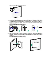
Page 22: ...crew into the screw anchor Leave 1 5 mm 0 06 in between the screw head and the wall for hanging the switch Figure 15 Installing the switch on a wall 2 3 Align the installation holes in the switch rear with the screws on the wall and hang the switch on the screws Make sure the port side faces down and the left and right sides are perpendicular to the ground Figure 16 Installing the switch on a wall...

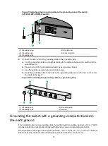
Page 23: ...ing conductor buried in the earth ground Grounding the switch by using the PE wire of the AC power cord NOTE The chassis views and power module and grounding terminal positions in the following figures are for illustration only Grounding the switch with a grounding strip WARNING Connect the grounding cable to the grounding system in the equipment room Do not connect it to a fire main or lightning ...

Page 24: ...Hook the grounding cable to the post on the grounding strip and use the hex nut to secure the cable to the post Figure 18 Connecting the grounding cable to a grounding strip 1 Grounding post 2 Grounding strip 3 Grounding cable 4 Hex nut Grounding the switch with a grounding conductor buried in the earth ground If the installation site has no grounding strips but earth ground is available hammer a ...

Page 25: ...r side The power cord is securely connected to the power outlet If the ground contact in the power outlet is not connected to the ground report the problem and reconstruct the grounding system NOTE To guarantee the grounding effect use the grounding cable provided with the switch to connect to the grounding strip in the equipment room Installing and removing a power module WARNING In power redunda...

Page 26: ... 4 Orient the power module with the lettering on it upright Grasp the handle of the power module with one hand and support its bottom with the other and slide the power module slowly into the slot along the guide rails See callout 1 in Figure 23 To prevent damage to the power module and the connector on the switch backplane insert the power module gently If you encounter a hard resistance or the p...

Page 27: ...odule on an antistatic mat or put it into its original packaging bag 6 If you are not to install a new power module install a filler panel in the slot Connecting the power cord WARNING Provide a circuit breaker for each power cord Before connecting the power cord make sure the circuit breaker on the power cord is turned off The S5560S 28F SI S5560S 28DP SI and S5130S 28F SI switches use removable ...

Page 28: ...ing the AC power cord for the fixed AC power module Connecting the AC power cord for the fixed AC power module 1 Connect the female connector of the AC power cord to the AC input power receptacle on the switch See Figure 24 2 Use a cable tie to secure the power cord to the handle near the AC input power receptacle See Figure 25 3 Connect the other end of the power cord to an AC power source Figure...

Page 29: ... 26 Connecting the DC power cord for the fixed DC power module S5120V2 28P HPWR LI switch Connecting the power cord for a PSR75 12A power module 1 Wear an ESD wrist strap Make sure the wrist strap makes good skin contact and is reliably grounded 2 Install the power cord retainer clip Insert the two ends of the clip into the holes in the brackets on the left of the power receptacle 3 Pull the power...

Page 30: ...space for heat dissipation around the switch and the rack or workbench is stable The grounding cable is securely connected The power source is as required by the switch The power cords are correctly connected If part of the network cable for a port is routed outdoors verify that a network port lightning protector is used for the port If a power line is routed from outdoors verify that a surge prot...

Page 31: ...are reachable to each other The PC must use an IP address different than VLAN interface 1 3 Start a browser on the PC enter http 192 168 0 233 in the address bar and press Enter The Web login page opens 4 Enter the default username admin and password admin and then click Login NOTE To log out do not close the browser directly You must click Logout at the top left corner on the Web interface Changi...

Page 32: ...a micro USB console cable yourself You can access the S5560S 28P SI switch S5560S 52P SI switch S5120V2 SI switch series S5120V2 LI switch series S5110V2 SI switch series S5000V3 EI switch series or S3100V3 SI switch series only from the serial console port Figure 29 Connecting the serial console port to a PC Connecting a serial console cable A serial console cable is an 8 core shielded cable with...

Page 33: ... To disconnect a PC from an operating switch first disconnect the switch end Connecting a micro USB console cable 1 Connect the standard USB connector to the USB port of the PC or configuration terminal 2 Connect the micro USB connector to the micro USB console port on the switch 3 Click the following link or copy it to the address bar on the browser to download the USB console driver http www h3c...

Page 34: ...26 Figure 31 Device Driver Installation Wizard 6 Click Continue Anyway if the following dialog box appears Figure 32 Software Installation 7 Click Finish ...

Page 35: ...s 1 Parity None Flow control None Starting the switch Pre start checklist Before powering on the switch verify that the following conditions are met The power cord is correctly connected The input power voltage meets the requirement of the switch The console cable is correctly connected The configuration terminal a PC for example has started and its serial port settings are consistent with the con...

Page 36: ...ee the software matching release notes for the device After the startup completes you can access the CLI to configure the switch For more information about the configuration commands and CLI see the configuration guides and command references for the switch series ...

Page 37: ... fabric Step Description 1 Plan IRF fabric setup Plan the installation site and IRF fabric setup parameters Planning IRF fabric size and the installation site Identifying the master switch and planning IRF member IDs Planning IRF topology and connections Identifying IRF physical ports on the member switches Planning the cabling scheme Start Plan IRF fabric setup Install IRF member switches Connect...

Page 38: ...nsity access Distribute the IRF member switches in different racks to implement the ToR access solution for a data center Identifying the master switch and planning IRF member IDs Determine which switch you want to use as the master for managing all member switches in the IRF fabric An IRF fabric has only one master switch You configure and manage all member switches in the IRF fabric at the CLI o...

Page 39: ...l ports can set up IRF connections only when operating at their highest speeds For example a 10 GE port must operate at 10 Gbps A 1 GE port must operate at 1 Gbps You can bind multiple ports to an IRF port for increased bandwidth and availability NOTE The following figures use the SFP ports on S5120V2 28P HPWR LI switches as an example For the ports that can be used for IRF connections see Table 8...

Page 40: ...are in the same group Ports in one group can be bound to different IRF ports The IRF physical ports on the member switches must be same type S5560S 28F SI S5130S 28F SI S5130S 28S HPWR LI All the following ports on the front panel 10 100 1000BASE T autosensing ports supported only in F6304 and later SFP ports supported only in F6304 and later SFP ports The port must operate at its highest speed 10...

Page 41: ... and LEDs SFP transceiver modules and optical fiber or SFP cable SFP ports For the available models see Appendix C Ports and LEDs If the IRF member switches are far away from one another use SFP SFP transceiver modules and optical fibers If the IRF member switches are all in one equipment room use twisted pair cables or SFP SFP cables The following subsections describe several H3C recommended IRF ...

Page 42: ...o IRF port 1 on one switch and to IRF port 2 on the other switch You perform IRF port binding before or after connecting IRF physical ports depending on the software release Execute the display irf configuration command to verify the basic IRF settings For more information about configuring basic IRF settings see the IRF configuration guide or virtual technologies configuration guide for the switc...

Page 43: ...member switches as if they were one node 5 Display the running status of the IRF fabric by using the commands in Table 9 Table 9 Displaying and maintaining IRF configuration and running status Task Command Display IRF fabric information display irf Display basic IRF settings for each member device display irf configuration Display IRF fabric topology information display irf topology NOTE To avoid ...

Page 44: ... EI PWR and S3100V3 28TP PWR SI switches RPS Steady green Both the RPS input and the AC input are normal Steady yellow Normal RPS input no or abnormal AC input Off No or abnormal DC input Input failure on an AC powered switch Symptom The system status LED on an AC powered switch is off Solution To resolve the issue 1 Verify that the AC power cord is securely connected to the switch and the AC inpu...

Page 45: ... to stop working and enter protection state 6 If the issue persists contact H3C Support Symptom 2 The system status LED on the RPS and AC powered switch is on but the RPS status LED is steady yellow Solution To resolve the issue 1 Verify that the AC power cord is securely connected to the switch and the AC input power receptacle on the switch and the connected AC power outlet are in good condition...

Page 46: ... Fan tray failure Symptom The system status LED on the switch indicates a fan tray failure Solution When a fan tray issue occurs contact H3C Support Configuration terminal issues No display on the configuration terminal Symptom The configuration terminal does not have display when the switch is powered on Solution To resolve the issue 1 Verify that the power system is operating correctly 2 Verify ...

Page 47: ...he configuration terminal displays garbled text Solution To resolve the issue 1 Verify that the following settings are configured for the terminal Baud rate 9600 Data bits 8 Parity None Stop bits 1 Flow control None 2 If the issue persists contact H3C Support ...

Page 48: ...28P SI Figure 40 Front panel 1 10 100 1000BASE T autosensing Ethernet port 2 10 100 1000BASE T autosensing Ethernet port LED 3 SFP port LED 4 System status LED SYS 5 Console port CONSOLE 6 SFP port Figure 41 Rear panel 1 Grounding screw 2 AC input power receptacle 1 5 2 3 6 4 2 1 ...

Page 49: ...rt LED 5 System status LED SYS 6 SFP port Figure 43 Rear panel 1 Grounding screw 2 AC input power receptacle S5560S 28S SI Figure 44 Front panel 1 10 100 1000BASE T autosensing Ethernet port 2 10 100 1000BASE T autosensing Ethernet port LED 3 SFP port LED 4 System status LED SYS 5 Micro USB console port 6 Console port CONSOLE 7 SFP port 1 2 3 6 5 4 1 2 1 5 7 2 3 6 4 ...

Page 50: ... Front panel 1 10 100 1000BASE T autosensing Ethernet port 2 10 100 1000BASE T autosensing Ethernet port LED 3 Console port CONSOLE 4 Micro USB console port 5 SFP port LED 6 System status LED SYS 7 SFP port Figure 47 Rear panel 1 Grounding screw 2 AC input power receptacle 2 1 1 2 3 4 5 6 7 1 2 ...

Page 51: ...PWR2 10 Power module 1 status LED PWR1 11 SFP port LED 12 Management Ethernet port LED ACT LINK 13 SFP port Figure 49 Rear panel 1 Grounding screw 2 Power module slot 1 PWR1 3 Power module slot 2 PWR2 An S5560S 28F SI switch comes with power module slot 1 installed with a PSR75 12A power module and power module slot 2 installed with a filler panel For information about installing and removing a po...

Page 52: ...odule 2 status LED PWR2 12 Power module 1 status LED PWR1 13 Management Ethernet port LED ACT LINK 14 SFP port LED Figure 51 Rear panel 1 Grounding screw 2 Power module slot 1 PWR1 3 Power module slot 2 PWR2 An S5560S 28DP SI switch comes with power module slot 1 installed with a PSR75 12A power module and power module slot 2 installed with a filler panel For information about installing and remov...

Page 53: ...o USB console port 6 Console port CONSOLE 7 SFP port Figure 53 Rear panel 1 Grounding screw 2 AC input power receptacle S5130S 52S SI S5130S 52S LI Figure 54 Front panel 1 10 100 1000BASE T autosensing Ethernet port 2 10 100 1000BASE T autosensing Ethernet port LED 3 Console port CONSOLE 4 Micro USB console port 5 SFP port LED 6 System status LED SYS 7 SFP port 1 5 7 2 3 6 4 2 1 1 2 3 4 5 6 7 ...

Page 54: ...s LED SYS 9 Power module 2 status LED PWR2 10 Power module 1 status LED PWR1 11 SFP port LED 12 Management Ethernet port LED ACT LINK 13 SFP port Figure 57 Rear panel 1 Grounding screw 2 Power module slot 1 PWR1 3 Power module slot 2 PWR2 An S5130S 28F SI switch comes with power module slot 1 installed with a PSR75 12A and power module slot 2 installed with a filler panel For information about ins...

Page 55: ...CONSOLE 9 SFP port Figure 59 Rear panel 1 Grounding screw 2 AC input power receptacle S5130S 28S HPWR LI Figure 60 Front panel 1 10 100 1000BASE T autosensing Ethernet port 2 SFP port 3 Console port CONSOLE 4 Mode button 5 10 100 1000BASE T autosensing Ethernet port LED 6 System status LED SYS 7 RPS status LED RPS 8 Mode LED MODE 9 SFP port LED 10 SFP port LED 11 Micro USB console port 12 SFP port...

Page 56: ... T autosensing Ethernet port 2 10 100 1000BASE T autosensing Ethernet port LED 3 Console port CONSOLE 4 Mode button 5 System status LED SYS 6 RPS status LED RPS 7 Mode LED MODE 8 Micro USB console port 9 SFP port 10 SFP port LED Figure 63 Rear panel 1 Grounding screw 2 AC input power receptacle 3 DC input power receptacle 1 2 3 1 3 4 6 2 5 7 8 10 9 1 2 3 ...

Page 57: ... LED 4 System status LED SYS 5 Console port CONSOLE 6 SFP port Figure 65 Rear panel 1 Grounding screw 2 AC input power receptacle S5120V2 20P LI Figure 66 Front panel 1 10 100 1000BASE T autosensing Ethernet port 2 10 100 1000BASE T autosensing Ethernet port LED 3 SFP port LED 4 System status LED SYS 5 Console port CONSOLE 6 SFP port 1 3 2 5 6 4 2 1 1 2 3 4 6 5 ...

Page 58: ...20V2 28P LI Figure 68 Front panel 1 10 100 1000BASE T autosensing Ethernet port 2 10 100 1000BASE T autosensing Ethernet port LED 3 SFP port LED 4 System status LED SYS 5 Console port CONSOLE 6 SFP port Figure 69 Rear panel 1 Grounding screw 2 AC input power receptacle 1 2 1 5 2 3 6 4 2 1 ...

Page 59: ...port LED 5 System status LED SYS 6 SFP port Figure 71 Rear panel 1 Grounding screw 2 AC input power receptacle S5120V2 10P PWR LI Figure 72 Front panel 1 10 100 1000BASE T autosensing Ethernet port 2 10 100 1000BASE T autosensing Ethernet port LED 3 SFP port LED 4 System status LED SYS 5 Mode LED MODE 6 Mode button 7 Console port CONSOLE 8 SFP port 1 2 3 6 5 4 1 2 1 3 2 5 6 8 4 7 ...

Page 60: ...Front panel 1 10 100 1000BASE T autosensing Ethernet port 2 Mode button 3 10 100 1000BASE T autosensing Ethernet port LED 4 SFP port LED 5 System status LED SYS 6 Mode LED MODE 7 Console port CONSOLE 8 SFP port Figure 75 Rear panel 1 Grounding screw 2 AC input power receptacle 1 2 1 7 3 8 6 2 4 5 1 2 ...

Page 61: ...LED MODE 8 SFP port LED 9 SFP port Figure 77 Rear panel 1 Grounding screw 2 AC input power receptacle 3 DC input power receptacle S5120V2 52P PWR LI Figure 78 Front panel 1 10 100 1000BASE T autosensing Ethernet port 2 10 100 1000BASE T autosensing Ethernet port LED 3 Console port CONSOLE 4 Mode button 5 System status LED SYS 6 RPS status LED RPS 7 Mode LED MODE 8 SFP port 9 SFP port LED 1 9 3 5 2...

Page 62: ... LI Figure 80 Front panel 1 10 100 1000BASE T autosensing Ethernet port 2 10 100 1000BASE T autosensing Ethernet port LED 3 SFP port LED 4 System status LED SYS 5 Mode LED MODE 6 Mode button 7 Console port CONSOLE 8 SFP port Figure 81 Rear panel 1 AC input power receptacle 2 Grounding screw 1 2 3 1 2 4 3 6 7 8 5 1 2 ...

Page 63: ...ystem status LED SYS 5 Console port CONSOLE 6 SFP port Figure 83 Rear panel 1 Grounding screw 2 AC input power receptacle S5110V2 52P SI Figure 84 Front panel 1 10 100 1000BASE T autosensing Ethernet port 2 10 100 1000BASE T autosensing Ethernet port LED 3 Console port CONSOLE 4 SFP port LED 5 System status LED SYS 6 SFP port 1 5 2 3 6 4 2 1 1 2 3 6 5 4 ...

Page 64: ...EI Figure 86 Front panel 1 10 100 1000BASE T autosensing Ethernet port 2 10 100 1000BASE T autosensing Ethernet port LED 3 SFP port LED 4 System status LED SYS 5 Console port CONSOLE 6 SFP port Figure 87 Rear panel 1 AC input power receptacle 2 Grounding screw 1 2 1 2 3 4 6 5 1 2 ...

Page 65: ...ystem status LED SYS 5 Console port CONSOLE 6 SFP port Figure 89 Rear panel 1 Grounding screw 2 AC input power receptacle S5048PV3 EI Figure 90 Front panel 1 10 100 1000BASE T autosensing Ethernet port 2 10 100 1000BASE T autosensing Ethernet port LED 3 Console port CONSOLE 4 SFP port LED 5 System status LED SYS 6 SFP port 1 5 2 3 6 4 2 1 1 2 3 6 5 4 ...

Page 66: ...ont panel 1 10 100 1000BASE T autosensing Ethernet port 2 Mode button 3 10 100 1000BASE T autosensing Ethernet port LED 4 SFP port LED 5 System status LED SYS 6 Mode LED MODE 7 Console port CONSOLE 8 SFP port Figure 93 Rear panel 1 Grounding screw 2 AC input power receptacle 1 2 1 7 3 8 6 2 4 5 1 2 ...

Page 67: ... port CONSOLE 8 SFP port Figure 95 Rear panel 1 Grounding screw 2 AC input power receptacle 3 DC input power receptacle S5048PV3 EI PWR Figure 96 Front panel 1 10 100 1000BASE T autosensing Ethernet port 2 10 100 1000BASE T autosensing Ethernet port LED 3 Console port CONSOLE 4 Mode button 5 System status LED SYS 6 RPS status LED RPS 7 Mode LED MODE 8 SFP port 9 SFP port LED 1 7 3 8 6 2 4 5 1 2 3 ...

Page 68: ...le S5024FV3 EI Figure 98 Front panel 1 SFP port 2 10 100 1000BASE T autosensing Ethernet port 3 SFP port LED 4 System status LED SYS 5 10 100 1000BASE T autosensing Ethernet port LED 6 Console port CONSOLE Figure 99 Rear panel 1 AC input power receptacle 2 Grounding screw 1 2 3 1 2 3 4 5 6 1 1 2 ...

Page 69: ...ort 7 Console port CONSOLE 8 SFP port 9 SFP port Figure 101 Rear panel 1 Grounding screw 2 AC input power receptacle S5500V3 48P SI Figure 102 Front panel 1 10 100 1000BASE T autosensing Ethernet port 2 10 100 1000BASE T autosensing Ethernet port LED 3 SFP port LED 4 Console port CONSOLE 5 Micro USB console port 6 SFP port LED 7 System status LED SYS 8 SFP port 9 SFP port 1 6 8 2 3 7 4 5 9 2 1 1 2...

Page 70: ...tosensing Ethernet port 2 10 100 1000BASE T autosensing Ethernet port 3 10 100BASE T autosensing Ethernet port LED 4 SFP port LED 5 System status LED SYS 6 10 100 1000BASE T autosensing Ethernet port LED 7 Console port CONSOLE 8 SFP port Figure 105 Rear panel 1 Grounding screw 2 AC input power receptacle 1 2 1 4 3 5 7 6 8 2 1 2 ...

Page 71: ...m status LED SYS 7 Console port CONSOLE 8 SFP port Figure 107 Rear panel 1 Grounding screw 2 AC input power receptacle S3100V3 28TP SI Figure 108 Front panel 1 10 100BASE T autosensing Ethernet port 2 10 100 1000BASE T autosensing Ethernet port 3 10 100BASE T autosensing Ethernet port LED 4 10 100 1000BASE T autosensing Ethernet port LED 5 SFP port LED 6 System status LED SYS 7 Console port CONSOL...

Page 72: ...tosensing Ethernet port 2 10 100BASE T autosensing Ethernet port LED 3 10 100 1000BASE T autosensing Ethernet port 4 10 100 1000BASE T autosensing Ethernet port LED 5 Console port CONSOLE 6 System status LED SYS 7 SFP port 8 SFP port LED Figure 111 Rear panel 1 Grounding screw 2 AC input power receptacle 1 2 1 5 6 3 7 8 2 4 2 1 ...

Page 73: ...ode button 9 Console port CONSOLE 10 SFP port Figure 113 Rear panel 1 AC input power receptacle 2 Grounding screw S3100V3 20TP PWR SI Figure 114 Front panel 1 10 100BASE T autosensing Ethernet port 2 10 100 1000BASE T autosensing Ethernet port 3 10 100BASE T autosensing Ethernet port LED 4 10 100 1000BASE T autosensing Ethernet port LED 5 SFP port LED 6 System status LED SYS 7 Mode LED MODE 8 Mode...

Page 74: ...autosensing Ethernet port 3 10 100BASE T autosensing Ethernet port LED 4 System status LED SYS 5 RPS status LED RPS 6 Mode LED MODE 7 SFP port LED 8 10 100 1000BASE T autosensing Ethernet port LED 9 Mode button 10 Console port CONSOLE 11 SFP port Figure 117 Rear panel 1 Grounding screw 2 AC input power receptacle 3 DC input power receptacle 1 2 1 3 4 5 2 9 6 10 11 7 8 2 1 3 ...

Page 75: ... N A N A 4 4 Input voltage Rated voltage 100 VAC to 240 VAC 50 or 60 Hz Max voltage 90 VAC to 264 VAC 47 to 63 Hz Minimum power consumption 9 W 18 W 10 W 19 W Maximum power consumption 23 W 41 W 24 W 44 W Chassis leakage current compliance UL60950 1 EN60950 1 IEC60950 1 GB4943 Melting current of power module fuse 2 A 250 V 3 15 A 250 V 2 A 250 V 3 15 A 250 V Cooling system Natural cooling without ...

Page 76: ...corresponding 10 100 1000BASE T autosensing Ethernet ports form combo interfaces SFP port 4 N A Power module slot 2 on the rear panel 2 on the rear panel Input voltage AC input Rated voltage range 100 VAC to 240 VAC 50 Hz or 60 Hz Max voltage range 90 VAC to 290 VAC 47 Hz to 63 Hz High voltage DC input Rated voltage range 240 VDC Max voltage range 180 VDC to 320 VDC AC input Rated voltage range 10...

Page 77: ...port N A 1 10 100 1000 BASE T autosensing Ethernet port 24 48 8 Each and its corresponding SFP port form a combo interface SFP port N A 24 The eight highest numbered SFP ports and their corresponding 10 100 1000BASE T autosensing Ethernet ports form combo interfaces SFP port 4 Power module slot N A 2 on the rear panel Input voltage Rated voltage 100 VAC to 240 VAC 50 or 60 Hz Max voltage 90 VAC to...

Page 78: ...tch models Item S5130S 28S PWR LI S5130S 52S PWR LI S5130S 28S HPWR LI Dimensions H W D 43 6 440 260 mm 1 72 17 32 10 24 in 43 6 440 400 mm 1 72 17 32 15 75 in 43 6 440 260 mm 1 72 17 32 10 24 in Weight 4 kg 8 82 lb 6 kg 13 23 lb 4 5 kg 9 92 lb Console port 1 micro USB console port 1 serial console port Only the micro USB console port is available when you connect both ports 10 100 1000 BASE T aut...

Page 79: ...is right side Using fixed fan trays to intake cool air from the chassis left side and port side and exhaust hot air from the chassis right side Operating temperature 5 C to 45 C 23 F to 113 F Operating humidity 5 RH to 95 RH noncondensing Fire resistance compliance UL60950 1 EN60950 1 IEC60950 1 GB4943 S5120V2 SI S5120V2 LI switch series Table 15 Technical specifications for the S5120V2 SI S5120V2...

Page 80: ...module side Operating temperature 5 C to 45 C 23 F to 113 F Operating humidity 5 RH to 95 RH noncondensing Fire resistance compliance UL60950 1 EN60950 1 IEC60950 1 GB4943 Table 16 Technical specifications for S5120V2 SI S5120V2 LI PoE switch models Item S5120V2 10P PWR LI S5120V2 28P PWR LI S5120V2 52P PWR LI S5120V2 28P HPWR LI S5120V2 12 TP HPWR LI Dimension s H W D 43 6 330 230 mm 1 72 12 99 9...

Page 81: ...put only for the S5120V2 28P HPWR LI and S5120V2 52P PWR LI switches Rated voltage 54 VDC to 57 VDC Max voltage Single DC input 44 VDC to 60 VDC AC and DC inputs 54 VDC to 57 VDC Maximum PoE power per port 30 W 30 W 30 W 30 W The combo copper ports do not support PoE power supply 30 W The combo copper ports do not support PoE power supply Total PoE power 125 W 170 W AC 370 W DC 740 W AC 370 W DC 7...

Page 82: ... the S5110V2 SI switch series Item S5110V2 28P SI S5110V2 52P SI Dimensions H W D 43 6 440 160 mm 1 72 17 32 6 30 in 43 6 440 230 mm 1 72 17 32 9 06 in Weight 2 5 kg 5 51 lb 3 5 kg 7 72 lb Console port 1 serial console port 1 serial console port 10 100 1000BASE T autosensing Ethernet port 24 48 SFP port 4 4 Input voltage Rated voltage 100 VAC to 240 VAC 50 or 60 Hz Max voltage 90 VAC to 264 VAC 47...

Page 83: ... interface SFP port 4 4 4 28 SFP ports 25 and 26 form combo interfaces with their corresponding 10 100 1000BASE T autosensing Ethernet port respectively Input voltage Rated voltage 100 VAC to 240 VAC 50 or 60 Hz Max voltage 90 VAC to 264 VAC 47 to 63 Hz Minimum power consumption 9 W 9 W 18 W 12 W Maximum power consumption 19 W 23 W 41 W 37 W Chassis leakage current compliance UL60950 1 EN60950 1 I...

Page 84: ...ltage AC input Rated voltage 100 VAC to 240 VAC 50 or 60 Hz Max voltage 90 VAC to 264 VAC 47 to 63 Hz H3C RPS1600 A DC input only for the S5024PV3 EI HPWR and S5048PV3 EI PWR switches Rated voltage 54 VDC to 57 VDC Max voltage Single DC input 44 VDC to 60 VDC AC and DC inputs 54 VDC to 57 VDC Maximum PoE power per port 30 W 30 W 30 W Total PoE power 170 W AC 370 W DC 740 W AC 370 W DC 740 W Minimu...

Page 85: ...micro USB console port is available when you connect both ports 1 micro USB console port 1 serial console port Only the micro USB console port is available when you connect both ports 10 100 1000BASE T autosensing Ethernet port 24 48 SFP port 2 2 SFP port 2 2 Input voltage Rated voltage 100 VAC to 240 VAC 50 or 60 Hz Max voltage 90 VAC to 264 VAC 47 to 63 Hz Minimum power consumption 10 W 19 W Max...

Page 86: ...serial console port 10 100BAS E T autosensing Ethernet port 4 8 16 32 10 100 1000 BASE T autosensing Ethernet port 4 8 8 16 SFP port 2 2 4 4 Input voltage Rated voltage 100 VAC to 240 VAC 50 or 60 Hz Max voltage 90 VAC to 264 VAC 47 to 63 Hz Minimum power consumption 6 5 W 7 W 9 W 18 W Maximum power consumption 11 W 15 W 19 W 33 W Chassis leakage current compliance UL60950 1 EN60950 1 IEC60950 1 G...

Page 87: ...g Ethernet port 4 8 16 10 100 1000 BASE T autosensing Ethernet port 4 8 12 The four highest numbered 10 100 1000BASE T autosensing Ethernet ports form combo interfaces with their corresponding SFP ports respectively SFP port 2 4 4 Each and its corresponding 10 100 1000BASE T autosensing Ethernet port form a combo interface Input voltage AC input Rated voltage 100 VAC to 240 VAC 50 or 60 Hz Max vol...

Page 88: ...al cooling without fan trays Using fixed fan trays to intake cool air from the chassis left side and exhaust hot air from the chassis right side Using fixed fan trays to intake cool air from the chassis left side and port side and exhaust hot air from the chassis right side Operating temperature 5 C to 45 C 23 F to 113 F Operating humidity 5 RH to 95 RH noncondensing Fire resistance compliance UL6...

Page 89: ...28DP SI and S5130S 28F SI switches Power module model Item Specification Remarks PSR75 12A AC input Rated input voltage 100 VAC to 240 VAC 50 Hz or 60 Hz For more information about the power modules see H3C PSR75 12A Power Module User Manual Max input voltage 90 VAC to 290 VAC 47 Hz to 63 Hz High voltage DC input Rated input voltage 240 VDC Max input voltage 180 VDC to 320 VDC Max output power 75 ...

Page 90: ...rogram Provides connection to an ASCII terminal Provides connection to the USB port of a local PC running terminal emulation program Management Ethernet port The S5560S 28F SI S5560S 28DP SI and S5130S 28F SI switches provide a management Ethernet port on the front panel You can connect this port to a PC or management station for loading and debugging software or remote management Table 25 Managem...

Page 91: ... Item Specification Connector type RJ 45 Port attribute 10 Mbps half full duplex 100 Mbps half full duplex 1000 Mbps full duplex MDI MDI X autosensing Max transmission distance 100 m 328 08 ft Transmission medium Category 5 or above twisted pair cable Compatible standards IEEE 802 3i 802 3u 802 3ab SFP port The S5560S 28P SI switch S5560S 52P SI switch S5560S 28F SI switch S5560S 28DP SI S5130S 28...

Page 92: ...es S3100V3 10TP SI S3100V3 18TP SI S3100V3 28TP SI and S3100V3 10TP PWR SI Table 28 GE SFP transceiver modules and cables GE SFP transceiver module cable Central wavelength Connector Cable specifications Modal bandwidth MHz km Max transmission distance Copper SFP transceiver module SFP GE T N A RJ 45 Twisted pair cable N A 100 m 328 09 ft SFP GE T D N A RJ 45 Twisted pair cable N A 100 m 328 09 ft...

Page 93: ...LH80 SM1 550 1550 nm LC 9 125 µm single mode optical fiber N A 80 km 49 71 miles SFP GE LH80 SM1 550 D 1550 nm LC 9 125 µm single mode optical fiber N A 80 km 49 71 miles SFP GE LH100 SM 1550 1550 nm LC 9 125 µm single mode optical fiber N A 100 km 62 14 miles SFP GE L X SM 1310 BIDI You must use these two transceiver modules in pairs TX 1310 nm RX 1490 nm LC 9 125 µm single mode optical fiber N A...

Page 94: ...X SM1 310 BIDI You must use these two transceiver modules in pairs TX 1310 nm RX 1550 nm LC 9 125 µm single mode 15 km 9 32 miles SFP FE LX SM1 550 BIDI TX 1550 nm RX 1310 nm LC NOTE As a best practice use H3C transceiver modules and cables for the switch H3C transceiver modules and cables are subject to change over time For the most up to date list of H3C transceiver modules and cables contact yo...

Page 95: ...6 m 216 54 ft 62 5 125 µm multi mode optical fiber 200 33 m 108 27 ft 160 26 m 85 30 ft SFP XG LX SM 1310 D 1310 nm LC 9 125 µm single mode optical fiber N A 10 km 6 21 miles SFP XG LX SM 1310 E 1310 nm LC 9 125 µm single mode optical fiber N A 10 km 6 21 miles SFP XG LH40 SM1550 1550 nm LC 9 125 µm single mode optical fiber N A 40 km 24 86 miles SFP XG LH40 SM1550 D 1550 nm LC 9 125 µm single mod...

Page 96: ...4FV3 EI switches each provide two combo interfaces on the front panel The S5560S 28F SI S5560S 28DP SI and S5130S 28F SI switches each provide eight combo interfaces on the front panel Each combo interface contains an SFP port and a 10 100 1000BASE T autosensing Ethernet port Only one of the two ports is active at a time LEDs System status LED The system status LED shows the operating status of th...

Page 97: ...e power module slot but the power module is faulty or no power is being supplied to the power module Off No power module is installed in the power module slot RPS status LED The S5130S 28S HPWR LI S5130S 52S PWR LI S5130S 28S HPWR LI S5130S 52S PWR LI S5120V2 28P HPWR LI S5120V2 52P PWR LI S5024PV3 EI HPWR S5048PV3 EI PWR and S3100V3 28TP PWR SI switches support RPS input These switches except the...

Page 98: ...0 100 1000BASE T autosensing Ethernet port LEDs work in conjunction with the mode LED to indicate the operating state of the 10 100BASE T autosensing Ethernet ports or 10 100 1000BASE T autosensing Ethernet ports and the switch from different aspects See Table 38 for the LED description Among the non PoE switch models only the S5560S 28DP S switch supports port LED mode switching The 10 100 1000BA...

Page 99: ...e if the LED for port 5 is steady green and the other port LEDs are off the IRF member ID of the switch is 5 Table 39 10 100 1000BASE T autosensing Ethernet port LED description Mode LED status 10 100 1000BASE T autosensing Ethernet port LED status Description Steady green Link Active mode Steady green A link is present on the port Flashing green The port is sending or receiving data Off No link i...

Reviews: