background image

Quick Start 
H3C S3610 Series Ethernet Switches

Chapter 3  Installing the Switch


3-2 


  Note: 

z


The front mounting ears are included in the standard configuration 
package, and the tray and the guide rails need to be ordered. 

z


When the switch is more than 300 mm (11.81 in.) in depth, the front 
mounting ears are not used for bearing but for fixing only. 

z


Ensure a clearance of 1U (44.45 mm, namely, 1.75 inches) 
between devices for the purpose of heat dissipation. 

z


Guide rails purchased from H3C apply only to standard cabinets 
1,000 mm (39.4 in) deep. Use other supports to substitute for guide 
rails in the case of other cabinet depths. 


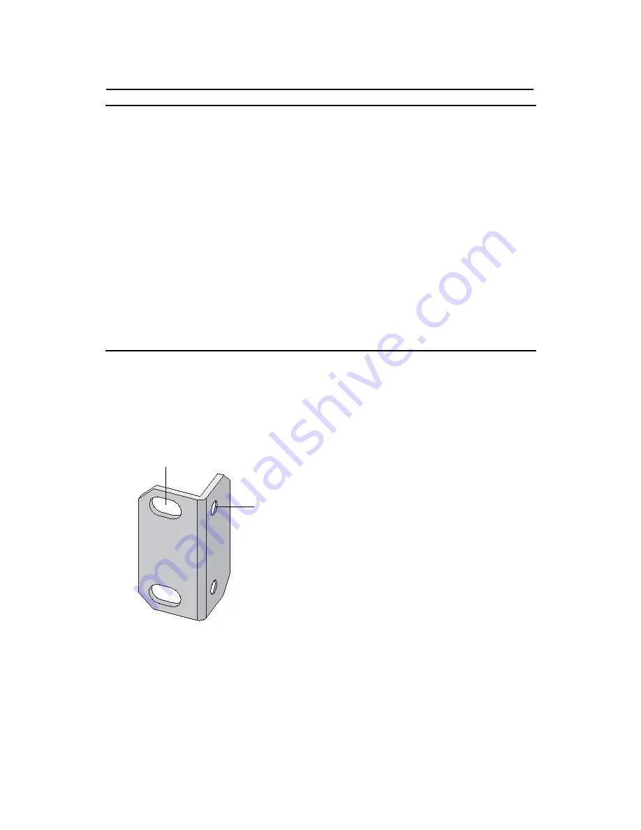
I. Introduction to mounting ear 

Figure 3-1 shows the appearance of a front mounting ear. 

(1)

(2)


(1): Screw hole used to fix the mounting ear to the cabinet (Use one M6 
screw) 
(2): Screw hole used to fix the switch to the mounting ear 

Figure 3-1 

Appearance of a standard front mounting ear 

Summary of Contents for S3610 Series

Page 1: ...H3C S3610 Series Ethernet Switches Quick Start Hangzhou H3C Technologies Co Ltd http www h3c com Manual Version T2 08225A 20080526 C 1 07...

Page 2: ...InnoVision and HUASAN are trademarks of Hangzhou H3C Technologies Co Ltd All other trademarks that may be mentioned in this manual are the property of their respective owners Notice The information i...

Page 3: ...cations H3C S3610 S5510 Series Ethernet Switches Command Manual It is used for assisting the users in using various commands H3C S3610 Series Ethernet Switches Installation Manual It is used for assis...

Page 4: ...ventions The manual uses the following conventions I Command conventions Convention Description Boldface The keywords of a command line are in Boldface italic Command arguments are in italic Items key...

Page 5: ...n names are inside angle brackets For example click OK Window names menu items data table and field names are inside square brackets For example pop up the New User window Multi level menus are separa...

Page 6: ...ntal Protection This product has been designed to comply with the requirements on environmental protection For the proper storage use and disposal of this product national laws and regulations must be...

Page 7: ...28P Ethernet Switch 1 5 1 3 1 Front Panel 1 5 1 3 2 Rear Panel 1 6 1 3 3 Power Supply System 1 6 1 3 4 Cooling System 1 6 1 4 S3610 28F Ethernet Switch 1 7 1 4 1 Front Panel 1 7 1 4 2 Rear Panel 1 7 1...

Page 8: ...ications of the S3610 Series 1 36 1 9 SFP modules 1 38 1 9 1 100 Mbps SFP modules 1 38 1 9 2 1000 Mbps SFP modules 1 38 Chapter 2 Installation Preparation 2 1 2 1 Safety Precautions 2 1 2 2 Installati...

Page 9: ...ting the Console Cable 3 21 3 4 Installation of the Optional Interface Modules 3 22 3 4 1 Installation of the Optional Interface Modules 3 22 3 4 2 Removal of Optional Interface Modules 3 23 3 5 Verif...

Page 10: ...of installation are required The S3610 series are designed to operate on the convergence and access layer of intranets and metropolitan area networks MANs They support both IPv4 and IPv6 and thus offe...

Page 11: ...0 Mbps uplink ports Console port S3610 28P AC input DC input 28 24 fixed 10Base T 100Ba se TX Ethernet ports 4 1000 Mbps SFP ports One S3610 28F AC input DC input 28 24 x 100 Mbps SFP ports 2 1000 Mbp...

Page 12: ...inserted interfac e module 52 at most Dependi ng on the inserted interface module up to 48 10 100 Mbps electrical ports or 48 100 Mbps SFP ports 4 1000 Mbps SFP ports 4 10 100 10 00 Mbps electrical p...

Page 13: ...tch button 7 Port mode switch LED 8 Power LED 9 DC input power LED Figure 1 1 Front panel of an S3610 28TP Ethernet switch 1 2 2 Rear Panel 1 2 3 1 2 3 1 AC input power socket 2 DC input power socket...

Page 14: ...stem S3610 28TP Ethernet switch provide one fan for heat dissipation 1 3 S3610 28P Ethernet Switch 1 3 1 Front Panel On its front panel the S3610 28P provides 24 fixed auto negotiation 10Base T 100Bas...

Page 15: ...P 1 3 3 Power Supply System The S3610 28P supports power load sharing between the AC and DC power supply It can also be powered by the AC power supply or DC power supply only I AC input Rated voltage...

Page 16: ...ne Console port as shown in Figure 1 5 1 100 Mbps SFP port status LEDs 2 1000 Mbps SFP port status LEDs 3 1000 Mbps Ethernet port status LEDs 4 Console port 5 7 segment numerical display 6 Port mode s...

Page 17: ...ge range 100 VAC to 240 VAC 50 Hz or 60 Hz Max voltage range 90 VAC to 264 VAC 50 Hz or 60 Hz II DC input Rated voltage range 48 V to 60 V Max voltage range 36 V to 72V 1 4 4 Cooling System S3610 28F...

Page 18: ...7 segment numerical display 4 Port mode switch button 5 Port mode switch LED 6 Power LED 7 DC input power LED 8 1000 Mbps SFP port status LEDs Figure 1 7 Front panel of the S3610 52P 1 5 2 Rear Panel...

Page 19: ...Hz II DC input Rated voltage range 48 V to 60 V Max voltage range 36 V to 72V 1 5 4 Cooling System S3610 52P Ethernet switch provide one fan for heat dissipation 1 6 S3610 52M S3610 52M DC Ethernet Sw...

Page 20: ...t swappable To install or remove these modules you must first power off the switch For how to install and remove these modules refer to section 3 4 Installation of the Optional Interface Modules 1 6 2...

Page 21: ...nals 1 2 3 4 1 Grounding screw 2 AC input power socket 3 RPS DC input redundancy power socket 4 Fixed interface module Figure 1 10 Rear panel of the S3610 52M II Rear panel of the S3610 52M DC switch...

Page 22: ...ce module Figure 1 11 Rear panel of the S3610 52M DC 1 6 3 Power Supply System I S3610 52M Rated voltage range 100 VAC to 240 VAC 50 Hz or 60 Hz Max voltage range 90 VAC to 264 VAC 50 Hz or 60 Hz II S...

Page 23: ...7 segment numerical display 24 x 10 100 Mbps Ethernet port status LEDs two 1000 Mbps SFP port status LEDs and two 10 100 1000 Mbps Ethernet port status LEDs on its front panel Table 1 2describes the...

Page 24: ...or is loading software 1 When running POST The system displays the number of current POST item on the 7 segment numerical display LED for example 2 When loading software the system lights the short ba...

Page 25: ...ber of the failed POST item on the 7 segment numerical display LED for example Flashing yellow at 1 Hz Some of the ports on the switch fails the POST and do not work OFF The switch is powered off Soli...

Page 26: ...ing In the process of POST The number of current POST item is displayed POST failure The number of the failed POST item is displayed Loading software The short bars are lighted one after another in cl...

Page 27: ...ata the LED flashes quickly Flashing yellow at 3 Hz The port fails the POST In speed mode OFF The port is disconnected Green The port works in full duplex mode when it receives sends data the LED flas...

Page 28: ...eceives sends data the LED flashes quickly Flashing yellow at 3 Hz The port fails the POST Speed OFF The port is disconnected Green The port works at 1000 Mbps in full duplex mode when it receives sen...

Page 29: ...s when it receives sends data the LED flashes quickly Flashing yellow at 3 Hz The port fails the POST Speed OFF The port is disconnected Green The port works in full duplex mode when it receives sends...

Page 30: ...input power LED one port mode switch LED one 7 segment numerical display 24 x 10 100 Mbps Ethernet port status LEDs and four 1000 Mbps SFP port status LEDs on its front panel Table 1 3 describes the m...

Page 31: ...or is loading software 1 When running POST The system displays the number of current POST item on the 7 segment numerical display LED for example 2 When loading software the system lights the short ba...

Page 32: ...the number of the failed POST item on the 7 segment numerical display LED for example Flashing yellow at 1 Hz Some of the ports fails the POST and do not work OFF The switch is powered off Solid green...

Page 33: ...Mark Status Meaning In the progress of POST The number of current POST item is displayed POST failure The number of failed POST item is displayed Loading software The short lines are lighted clockwise...

Page 34: ...sends data the LED flashes quickly Flashing yellow at 3 Hz The port fails the POST Speed OFF The port is disconnected Green The port works in full duplex mode when it receives sends data the LED flash...

Page 35: ...s at 1000 Mbps in full duplex mode when it receives sends data the LED flashes quickly Flashing yellow at 3 Hz The port fails the POST 1000 Base SFP port status LED Duplex OFF The port is disconnected...

Page 36: ...on its front panel Table 1 4 describes the meanings of these LEDs Table 1 4 LEDs on the front panel of the S3610 28F LED Mark Status Meaning Speed Solid green The port status LEDs are showing their cu...

Page 37: ...or is loading software 1 When running POST The system displays the number of current POST item on the 7 segment numerical display LED for example 2 When loading software the system lights the short ba...

Page 38: ...the number of the failed POST item on the 7 segment numerical display LED for example Flashing yellow at 1 Hz Some of the ports fails the POST and do not work OFF The switch is powered off Solid green...

Page 39: ...Mark Status Meaning In the progress of POST The number of current POST item is displayed POST failure The number of failed POST item is displayed Loading software The short lines are lighted clockwis...

Page 40: ...eceives sends data the LED flashes quickly Flashin g yellow at 3 Hz The port fails the POST Speed OFF The port is disconnected Green The port works at 100 Mbps in full duplex mode when it receives sen...

Page 41: ...ceives sends data the LED flashes quickly Flashin g yellow at 3 Hz The port fails the POST Speed OFF The port is disconnected Green The port works at 1000 Mbps in full duplex mode when it receives sen...

Page 42: ...when it receives sends data the LED flashes quickly Flashin g yellow at 3 Hz The port fails the POST Speed OFF The port is disconnected Green The port works in full duplex mode when it receives sends...

Page 43: ...t status LEDs on its front panel See Table 1 3 for the meanings of these LEDs 1 7 5 LEDs of the S3610 52M S3610 52M DC Ethernet switch The S3610 52M S3610 52M DC switch provides one power LED only on...

Page 44: ...ans data is being transceived Table 1 6 Meaning of LEDs on 10Base T 100Base TX module panel LED State LINK OFF means that the line is disconnected ON means the line is connected ACTIVE OFF means that...

Page 45: ...6KG 3 8KG 3 8KG 8 5 kg 18 7 lb Mana geme nt port One Console port Servic e port 24 10 10 0 Mbps electri cal ports 2 1 000 Mbps SFP ports 2 10 10 0 1 00 0 Mbps electri cal ports 24 10 10 0 Mbps electri...

Page 46: ...e S3610 series can be AC powered or DC powered AC Rated voltage range 100 VAC to 240 VAC 50 Hz or 60 Hz Maximum voltage range 90 VAC to 264 VAC 50 Hz or 60 Hz DC Rated voltage range 60 V to 48 V Maxim...

Page 47: ...M1310 A z SFP FE LH40 SM1310 z SFP FE LH80 SM1550 100 Mbps BIDI module z SFP FE LX SM1310 BIDI z SFP FE LX SM1550 BIDI 1 9 2 1000 Mbps SFP modules Table 1 10 1000 Mbps SFP modules supported by S3610 E...

Page 48: ...over time Consult H3C marketing personnel or technical support personnel to obtain the latest information about SFP modules z For specifications of SFP modules refer to H3C Low End Series Ethernet Swi...

Page 49: ...an unstable case or desk The switch might be damaged severely in case of a fall z Ensure proper ventilation of the equipment room and keep the ventilation vents of the switch free of obstruction z Mak...

Page 50: ...ty is two low captive screws may become loose as the result of contraction of insulation washers and static electricity may be produced in a dry environment to jeopardize the CMOS circuits on the devi...

Page 51: ...on and aging of metals such as salts acids and sulfides as shown in the following table Table 2 2 Harmful gas limits in the equipment room Gas Maximum concentration mg m3 SO2 0 2 H2S 0 006 NH3 0 05 Cl...

Page 52: ...elding when necessary for example use shielded interface cables z Route interface cables only indoors to prevent signal ports from getting damaged by overvoltage or overcurrent caused by lightning str...

Page 53: ...Quick Start H3C S3610 Series Ethernet Switches Chapter 2 Installation Preparation 2 5 z ESD preventive wrist strap Caution The installation tools are not provided with the S3610 series...

Page 54: ...screw of the switch chassis is intact If you want to open the chassis you should contact the agent for permission Otherwise you will bear any consequence resulted from your actions without permission...

Page 55: ...re a clearance of 1U 44 45 mm namely 1 75 inches between devices for the purpose of heat dissipation z Guide rails purchased from H3C apply only to standard cabinets 1 000 mm 39 4 in deep Use other su...

Page 56: ...position of the switch Cooling hole Used for heat dissipation between switch and cabinet Slotted hole 2 Used to fix the guide rail to the front bracket Figure 3 2 Appearance of a guide rail III Use fr...

Page 57: ...he cabinet 2 Take out the screws which are packed together with the front mounting ears and fix one end of mounting ears to the switch as shown in Figure 3 3 Figure 3 3 Fix front mounting ears 1 3 Pla...

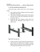
Page 58: ...ard cabinet 1 Wear an ESD preventive wrist strap to check the grounding and stability of the cabinet 2 Fix the delivered tray horizontally in a proper position 3 Take out the screws which are packed t...

Page 59: ...gether with the front mounting ears and fix one end of the front mounting ears to the switch as shown in Figure 3 3 3 Install guide rails on the brackets on both sides of the cabinet with M5 self tapp...

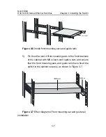
Page 60: ...guide rails 5 Fix the other end of front mounting ears to the front brackets of the cabinet with M6 screws and captive nuts and ensure that the front mounting ears and guide rails have fixed the swit...

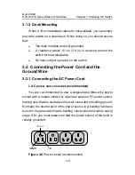
Page 61: ...e switch 3 2 Connecting the Power Cord and the Ground Wire 3 2 1 Connecting the AC Power Cord I AC power source socket recommended You are recommended to use a single phase three wire power socket wit...

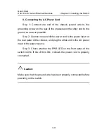
Page 62: ...end to the ground as near as possible Step 2 Connect one end of the power cord to the power input on the rear panel of the chassis and plug the other end to the AC power input of the power source Ste...

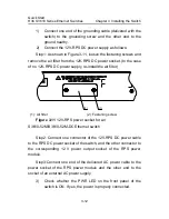
Page 63: ...the S3610 52M DC switch Step 1 Connect one end of the grounding wire delivered with the switch to the grounding screw and the other end to the ground nearby Step 1 Use a flat blade screwdriver to loos...

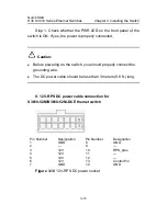
Page 64: ...aution z Before powering on the switch you should properly connect the grounding wire z The DC power cable should be less than 3 meters 9 8 ft long II 12V RPS DC power cable connection for S3610 52M S...

Page 65: ...wer supply re install the air filter 2 1 1 Air filter 2 Fastening screw Figure 3 11 12V RPS power socket for an S3610 52M S3610 52M DC Ethernet switch Step2 Connect one connector of the 12V RPS DC pow...

Page 66: ...ong z Only the recommended 12V RPS DC power supply and power cables can be used III DC power cable connection for S3610 28TP S3610 28P S3610 28F S3610 52P Ethernet switch NULL NULL 48V working ground...

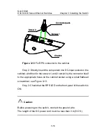
Page 67: ...rectly insert the component into DC input socket on the cabinet and then fix the screws 1 and 2 carried by the connector itself to the appropriate holes on the cabinet socket using a small flathead sc...

Page 68: ...n as PGND This chassis ground must be securely connected to the earth ground so that the faradism and leakage electricity can be safely released to the ground enhancing the EMS capability of the switc...

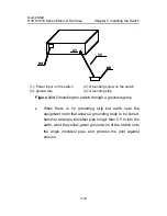
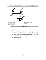
Page 69: ...wire 4 Grounding strip Figure 3 14 Grounding the switch through a grounding strip z When there is no grounding strip but earth near the equipment room that allows a grounding body to be buried hammer...

Page 70: ...4 Earth 5 Angel iron Figure 3 15 Grounding the switch by burying the grounding body into the earth z For an AC powered switch if none of the above two conditions is available ground it through the PE...

Page 71: ...re 5 AC input with 3 wire cable 6 Ethernet Switch Figure 3 16 Grounding through the AC PE wire z For a DC powered switch if none of the first two conditions is available ground it through the return w...

Page 72: ...V strip 3 48V 4 RTN strip 5 RTN 6 PGND strip 7 Grounding 8 Ground wire 9 Grounding screw 10 Ethernet Switch 11 DC input Figure 3 17 Grounding through the PGND of a power cabinet 3 2 4 Multi power Inpu...

Page 73: ...able At one end of the cable is a crimped RJ 45 connector for the connection to the Console port of the switch at the other end of the cable is one DB 9 female connector for the connection to the seri...

Page 74: ...steps to connect a terminal device a PC for example to the switch Step 1 Plug the DB 9 female connector of the Console cable to the serial port of the PC where the switch is to be configured Step 2 Co...

Page 75: ...e PC and then the RJ45 connector to the switch In disconnecting them remove the RJ 45 connector prior to the DB 9 connector 3 4 Installation of the Optional Interface Modules 3 4 1 Installation of the...

Page 76: ...rface card gently into the switch until the card touches the switch panel Step 5 Fix the interface card in the switch with the captive screws Caution Save the removed blank filler panel for future use...

Page 77: ...ule is removed and there is no need to mount a new one mount the blank filler panel in time to keep the dust out and ensure the normal ventilation of the switch 3 5 Verifying Installation z The correc...

Page 78: ...ith the switch You should purchase it by yourself if needed If an outdoor AC power cord should be directly led to the switch please serially connect the lightning arrester for AC power Socket Strip wi...

Page 79: ...nected Please check the power supply circuit Power switch Normal operation indicator green On means that the arrester works normally Otherwise it means that the protection circuit has been damaged Mul...

Page 80: ...he problem whether it is caused because the ground wire of the arrester is not well grounded or because the live and zero wires are connected in reverse direction You may check that in the following w...

Page 81: ...case Caution Lightning arrester for network port will not be provided along with the switch and you should purchase it by yourself if needed If an outdoor network cable should be led to the switch pl...

Page 82: ...ground wire to the grounding screw of the switch Step 3 Use the multimeter to measure whether the ground wire of the arrester contacts well with the grounding screw of chassis Step 4 According to the...

Page 83: ...allation precautions Fully consider the following items in the installation process otherwise the performance of the lightning arrester for network port will be affected Lightning arrester for network...

Page 84: ...on of the Switch 4 7 The lightning arrester for the network port is not installed completely If the switch has more than one network ports to interconnect with other devices via cables outdoor you sho...

Reviews: