background image


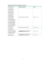
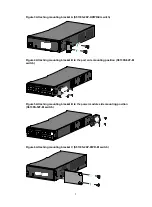
Table 3 Mounting brackets applicable to the switch 

Switch model 

Mounting brackets 

Views 

S5130S-28P-EI 
S5130S-28P-EI-M 
S5130S-28TP-EI 
S5130S-52P-EI 
S5130S-52P-EI-M 
S5130S-52TP-EI 
S5130S-28S-EI 
S5130S-28S-EI-M 
S5130S-52S-EI 
S5130S-52S-EI-M 
S5130S-28P-PWR-EI 
S5130S-28P-HPWR-EI 
S5130S-52P-PWR-EI 
S5130S-28S-PWR-EI 
S5130S-28S-HPWR-EI 
S5130S-52S-PWR-EI 

Mounting brackets A (provided) 

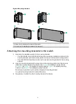
See A in 

Figure 2

S5130S-28F-EI 
S5130S-52F-EI 

Mounting brackets B (provided) 

See B in 

Figure 2

S5130S-20P-EI 
S5130S-10P-HPWR-EI 
S5130S-12TP-HPWR-EI 
S5130S-20P-PWR-EI 

Mounting brackets C with product code 

SOHO-SWITCH-FL-02

 (optional) 

See C in 

Figure 2

S5130S-10P-EI 
S5130S-12TP-EI 

Mounting brackets D with product code 

SOHO-SWITCH-FL-01 

(optional) 

See D in 

Figure 2


Summary of Contents for S5130S-EI series

Page 1: ...H3C S5130S EI Switch Series Installation Guide New H3C Technologies Co Ltd http www h3c com Document version 6W102 20180205...

Page 2: ...ay be mentioned in this manual are the property of their respective owners Notice The information in this document is subject to change without notice All contents in this document including statement...

Page 3: ...syntax choices keywords or arguments that are optional x y Braces enclose a set of required syntax choices separated by vertical bars from which you select one x y Square brackets enclose a set of op...

Page 4: ...switch such as a Layer 2 or Layer 3 switch or a router that supports Layer 2 forwarding and other Layer 2 features Represents an access controller a unified wired WLAN module or the access controller...

Page 5: ...Documentation feedback You can e mail your comments about product documentation to info h3c com We appreciate your comments...

Page 6: ...witch with fixed power modules 17 Connecting the power cord for a PSR75 12A PSR150 A1 power module 18 Connecting the power cord for a PSR150 D1 power module 19 Verifying the installation 20 Accessing...

Page 7: ...M 41 S5130S 52S EI S5130S 52S EI M 41 S5130S 10P HPWR EI 42 S5130S 12TP HPWR EI 43 S5130S 20P PWR EI 43 S5130S 28P PWR EI 44 S5130S 28P HPWR EI 45 S5130S 52P PWR EI 46 S5130S 28S PWR EI 46 S5130S 28S...

Page 8: ...odels and accessories vary by country and region This document describes only the preceding models For the chassis models and accessories available in your country or region contact the local H3C mark...

Page 9: ...ure and humidity in the equipment room as described in Technical specifications Lasting high relative humidity can cause poor insulation electricity leakage mechanical property change of materials and...

Page 10: ...m radio transmitting stations radar stations and high frequency devices to make sure the EMI levels do not exceed the compliant range Use electromagnetic shielding when necessary For example use shiel...

Page 11: ...nstallation flow Installing the switch in a 19 inch rack Mounting brackets Table 3 describes the mounting brackets applicable to the switch Ground the switch Install the switch Start Connect power cor...

Page 12: ...HPWR EI S5130S 52P PWR EI S5130S 28S PWR EI S5130S 28S HPWR EI S5130S 52S PWR EI Mounting brackets A provided See A in Figure 2 S5130S 28F EI S5130S 52F EI Mounting brackets B provided See B in Figure...

Page 13: ...The other S5130S EI switches provide only the port side mounting position for the mounting brackets 2 Align one mounting bracket with the screw holes at the mounting position Use M4 screws to attach...

Page 14: ...tch Figure 4 Attaching mounting bracket B to the port side mounting position S5130S 52F EI switch Figure 5 Attaching mounting bracket B to the power module side mounting position S5130S 52F EI switch...

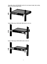
Page 15: ...ck posts No cage nuts are provided with the switch Prepare them yourself 4 One person holds the switch chassis and aligns the mounting brackets with the mounting holes in the rack posts and the other...

Page 16: ...ing an S5130S 52F EI switch in the rack power module side mounting position for the mounting brackets Figure 10 Mounting an S5130S 20P PWR EI switch in the rack Figure 11 Mounting an S5130S 10P EI swi...

Page 17: ...electrical lines exist in the wall Leave a minimum clearance of 10 mm 0 39 in around the chassis for heat dissipation Table 4 describes the switch models that support wall mounting and installation h...

Page 18: ...to fasten the screw into the screw anchor Leave 1 5 mm 0 06 in between the screw head and the wall for hanging the switch Figure 14 Installing the switch on a wall 2 3 Align the installation holes in...

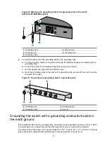
Page 19: ...ng conductor buried in the earth ground Grounding the switch by using the PE wire of the AC power cord NOTE The chassis views and power module and grounding terminal positions in the following figures...

Page 20: ...d Hook the grounding cable to the post on the grounding strip and use the hex nut to secure the cable to the post Figure 17 Connecting the grounding cable to a grounding strip 1 Grounding post 2 Grou...

Page 21: ...e power cord is securely connected to the power outlet If the ground contact in the power outlet is not connected to the ground report the problem and reconstruct the grounding system NOTE To guarante...

Page 22: ...le slot 2 4 Orient the power module with the upside up Grasp the handle of the power module with one hand and support its bottom with the other and slide the power module slowly along the guide rails...

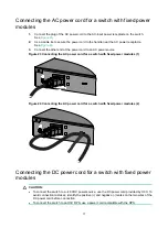
Page 23: ...S PWR EI AC power source Connecting the AC power cord for a switch with fixed power modules H3C RPS1600 A Connecting the DC power cord for a switch with fixed power modules S5130S 28F EI S5130S 52F EI...

Page 24: ...source Figure 23 Connecting the AC power cord for a switch with fixed power modules 1 Figure 24 Connecting the AC power cord for a switch with fixed power modules 2 Connecting the DC power cord for a...

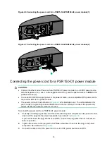
Page 25: ...an RPS Figure 25 Connecting the DC power cord for a switch with fixed power modules S5130S 52P PWR EI Connecting the power cord for a PSR75 12A PSR150 A1 power module 1 Pull the bail latch leftward as...

Page 26: ...code scheme in Figure 28 is for illustration only The cable delivered for your country or region might use a different color scheme When you connect the power cord always identify the polarity symbol...

Page 27: ...eat dissipation around the switch and the rack or workbench is stable The grounding cable is securely connected The correct power source is used The power cords are correctly connected All the interfa...

Page 28: ...ou can access other S5130S EI switch models only through the serial console port No serial console cable or micro USB console cable is provided with the switch Prepare yourself or purchase it from H3C...

Page 29: ...tch first connect the PC end To disconnect a PC from an operating switch first disconnect the switch end Connecting the micro USB console cable 1 Connect the standard USB connector to the USB port of...

Page 30: ...23 Figure 31 Device Driver Installation Wizard 6 Click Continue Anyway if the following dialog box appears Figure 32 Software Installation 7 Click Finish...

Page 31: ...or these programs The following are the required terminal settings Bits per second 9 600 Data bits 8 Stop bits 1 Parity None Flow control None Powering on the switch Before powering on the switch veri...

Page 32: ...e and menu options differ with software versions For more information about Boot ROM menu options see the software matching release notes for the device After the startup completes you can access the...

Page 33: ...geability IRF fabric setup flowchart Figure 34 IRF fabric setup flowchart To set up an IRF fabric Step Description 1 Plan IRF fabric setup Plan the installation site and IRF fabric setup parameters Pl...

Page 34: ...ermine which switch you want to use as the master for managing all member switches in the IRF fabric An IRF fabric has only one master switch You configure and manage all member switches in the IRF fa...

Page 35: ...GE SFP ports to an IRF port for increased bandwidth and availability NOTE The following figures use the SFP ports on the S5130S 28P HPWR EI switch as an example For the ports that can be used for IRF...

Page 36: ...sure the ports are in the same group GE ports in one group can be bound to different IRF ports Other S5130S EI switches The ports must operate at 1 Gbps Planning the cabling scheme Use the following c...

Page 37: ...ution You can install IRF member switches in different racks side by side to deploy a top of rack ToR solution Figure 39 shows an example for connecting four top of rack IRF member switches by using S...

Page 38: ...odules and Network Cables Installation Guide Verifying the IRF fabric setup To verify the basic functionality of the IRF fabric after you finish configuring basic IRF settings and connecting IRF ports...

Page 39: ...ng normally Steady yellow RPS power input is normal but AC input has failed or AC input is not connected Off No RPS is connected AC input failure Symptom The system status LED is off Solution To resol...

Page 40: ...use the power module to stop working and enter the protection state 6 If the issue persists contact H3C Support Symptom 2 The system status LED is on but the RPS status LED is steady yellow Solution T...

Page 41: ...tem status LED on the switch indicates a fan tray failure Solution When a fan tray issue occurs contact H3C Support Configuration terminal issues No display on the configuration terminal Symptom The c...

Page 42: ...e configuration terminal displays garbled text Solution To resolve the issue 1 Verify that the following settings are configured for the terminal Baud rate 9600 Data bits 8 Parity None Stop bits 1 Flo...

Page 43: ...ews S5130S 10P EI Figure 40 Front panel 1 10 100 1000BASE T autosensing Ethernet port 2 10 100 1000BASE T autosensing Ethernet port LED 3 SFP port LED 4 System status LED SYS 5 Console port 6 SFP port...

Page 44: ...LED 3 SFP port LED 4 System status LED SYS 5 Console port 6 SFP port Figure 43 Rear panel 1 Grounding screw 2 AC input power receptacle S5130S 20P EI Figure 44 Front panel 1 10 100 1000BASE T autosens...

Page 45: ...S 28P EI S5130S 28P EI M Figure 46 Front panel 1 10 100 1000BASE T autosensing Ethernet port 2 10 100 1000BASE T autosensing Ethernet port LED 3 SFP port LED 4 System status LED SYS 5 Console port 6 S...

Page 46: ...T autosensing Ethernet port LED 6 System status LED SYS 7 SFP port LED Figure 49 Rear panel 1 Grounding screw 2 AC input power receptacle S5130S 52P EI S5130S 52P EI M Figure 50 Front panel 1 10 100 1...

Page 47: ...52 Front panel 1 10 100 1000BASE T autosensing Ethernet port 2 10 100 1000BASE T autosensing Ethernet port LED 3 Console port 4 Micro USB console port 5 System status LED SYS 6 SFP port LED 7 SFP por...

Page 48: ...m status LED SYS 5 Micro USB console port 6 Console port 7 SFP port Figure 55 Rear panel 1 Grounding screw 2 AC input power receptacle S5130S 52S EI S5130S 52S EI M Figure 56 Front panel 1 10 100 1000...

Page 49: ...58 Front panel 1 10 100 1000BASE T autosensing Ethernet port 2 10 100 1000BASE T autosensing Ethernet port LED 3 SFP port LED 4 System status LED SYS 5 Mode LED MODE 6 Port LED mode switching button 7...

Page 50: ...LED MODE 6 Port LED mode switching button 7 Console port 8 SFP port Figure 61 Rear panel 1 AC input power receptacle 2 Grounding screw S5130S 20P PWR EI Figure 62 Front panel 1 10 100 1000BASE T auto...

Page 51: ...e 64 Front panel 1 10 100 1000BASE T autosensing Ethernet port 2 Port LED mode switching button 3 10 100 1000BASE T autosensing Ethernet port LED 4 SFP port LED 5 System status LED SYS 6 Mode LED MODE...

Page 52: ...port 2 Console port 3 Port LED mode switching button 4 10 100 1000BASE T autosensing Ethernet port LED 5 System status LED SYS 6 RPS status LED RPS 7 Mode LED MODE 8 SFP port LED 9 SFP port Figure 67...

Page 53: ...s LED RPS 7 Mode LED MODE 8 SFP port 9 SFP port LED Figure 69 Rear panel 1 Grounding screw 2 AC input power receptacle 3 DC input power receptacle S5130S 28S PWR EI Figure 70 Front panel 1 10 100 1000...

Page 54: ...hernet port 2 SFP port 3 Console port 4 Port LED mode switching button 5 10 100 1000BASE T autosensing Ethernet port LED 6 System status LED SYS 7 RPS status LED RPS 8 Mode LED MODE 9 SFP port LED 10...

Page 55: ...1000BASE T autosensing Ethernet port LED 3 Console port 4 Port LED mode switching button 5 System status LED SYS 6 RPS status LED RPS 7 Mode LED MODE 8 Micro USB console port 9 SFP port 10 SFP port L...

Page 56: ...SFP port LED 12 Management Ethernet port LED ACT LINK 13 SFP port Figure 77 Rear panel 1 Grounding screw 2 Power module 1 PWR1 3 Power module 2 PWR2 The S5130S 28F EI switch comes with no power modul...

Page 57: ...dule slot 1 and with a filler panel in power module slot 2 You can install one or two power modules for the switch as needed In Figure 79 two PSR150 A1 AC power modules are installed For information a...

Page 58: ...43 Melting current of power module fuse 2 A 250 V 2 A 250 V 2 A 250 V Cooling system Natural cooling without fan trays Natural cooling without fan trays Natural cooling without fan trays Operating tem...

Page 59: ...ole port 1 serial console port 1 micro USB console port When both ports are connected only the micro USB console port is available 1 serial console port 1 micro USB console port When both ports are co...

Page 60: ...ed air out from the power module side Using fixed fan trays to draw ambient air in from the left side and exhaust heated air out from the right side and power module side Operating temperature 0 C to...

Page 61: ...e equipment room or an RPS H3C RPS800 A or RPS1600 A Minimum power consumption 1 PSR75 12A 15 W 2 PSR75 12A 17 W 1 PSR150 A1 18 W 1 PSR150 D1 18 W 2 PSR150 A1 23 W 2 PSR150 D1 22 W 1 PSR75 12A 26 W 2...

Page 62: ...t ports respectively 4 Input voltage Rated voltage 100 VAC to 240 VAC 50 or 60 Hz Max voltage 90 VAC to 264 VAC 47 to 63 Hz Maximum PoE power per port 30 W 30 W The combo copper ports on an S5130S 12T...

Page 63: ...m a combo interface Input voltage Rated voltage 100 VAC to 240 VAC 50 or 60 Hz Max voltage 90 VAC to 264 VAC 47 to 63 Hz AC power source Rated voltage 100 VAC to 240 VAC 50 or 60 Hz Max voltage 90 VAC...

Page 64: ...24 in Weight 4 kg 8 82 lb 6 kg 13 23 lb 4 5 kg 9 92 lb Console port 1 serial console port 1 micro USB console port When both ports are connected only the micro USB console port is available 10 100 100...

Page 65: ...g system Using fixed fan trays to draw ambient air in from the left side and port side and exhaust heated air from the right side Using fixed fan trays to draw ambient air in from the left side and ex...

Page 66: ...I switch Table 17 Power modules available for the S5130S 52F EI switch Power module model Item Specification Remarks PSR75 12A Rated input voltage AC 100 VAC to 240 VAC 50 Hz or 60 Hz DC 240 VDC For m...

Page 67: ...s Provides connection to an ASCII terminal Provides connection to the serial port of a local PC running terminal emulation program Provides connection to an ASCII terminal Provides connection to the U...

Page 68: ...WR EI SFP ports 9 and 10 GE SFP transceiver module and cables in Table 21 and FE SFP transceiver modules in Table 22 SFP ports 11 and 12 GE SFP transceiver module and cables in Table 21 To use GE tran...

Page 69: ...g conditions are met The switch uses one or two PSR75 12A power modules for power supply The switch uses transceiver modules Table 21 GE SFP transceiver modules and cables GE SFP transceiver module ca...

Page 70: ...1490 nm LC 9 125 m single mode optical fiber N A 10 km 6 21 miles SFP G E LX S M1490 BIDI TX 1490 nm RX 1310 nm N A SFP cable SFP STACK Kit N A N A SFP cable N A 1 5 m 4 92 ft Table 22 FE SFP transce...

Page 71: ...GE SFP transceiver modules in Table 23 10 GE SFP cables in Table 24 Table 23 10 GE SFP transceiver modules available for the SFP ports 10 GE SFP transceiver module Central wavelength Connector Fiber...

Page 72: ...ovide four combo interfaces The S5130S 12TP EI S5130S 28TP EI S5130S 52TP EI S5130S 12TP HPWR EI and S5130S 52F EI switches each provide two combo interfaces The S5130S 28F EI switch provides eight co...

Page 73: ...Both the RPS DC input and the AC input are normal Steady yellow The RPS DC input is normal but the AC input is disconnected or has failed Off The RPS DC input has failed or no RPS is connected Mode L...

Page 74: ...No link is present on the port Flashing green PoE mode Steady green PoE power supply is normal Flashing green 1 Hz The maximum PoE power provided by the port fails to meet the power requirement of the...

Page 75: ...31 switch 21 troubleshooting configuration terminal issues 34 verify the IRF fabric setup 31 connecting 48 VDC power source 19 AC power source 17 18 console cable 21 first time switch access 21 IRF me...

Page 76: ...face technical specifications 65 connecting 48 VDC power source 19 connecting AC power source 17 18 console port technical specifications 60 grounding switch 12 grounding switch through AC power modul...

Page 77: ...y parameter 24 PE wire 14 physical port connecting 31 identifying IRF member switch physical ports 28 planning IRF cabling scheme 29 29 IRF connections 27 IRF member IDs 27 IRF topology 27 port 100 10...

Page 78: ...uration environment 21 terminal parameters 24 SFP port 64 site cleanliness 2 dust concentration 2 examining installation site 2 gas saturation 2 humidity 2 IRF fabric installation site planning 27 tem...

Page 79: ...ubleshooting garbled terminal display 35 troubleshooting no terminal display 34 tools needed for installation 3 topology planning IRF cabling scheme 29 29 topology IRF fabric 27 troubleshooting config...

Reviews: