16
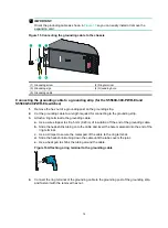
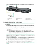
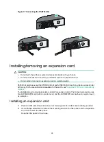
Figure 19 Grounding the switch by burying the grounding conductor into the earth ground
(1) Grounding screw
(2) Chassis rear panel
(3) Grounding cable
(4) Earth
(5) Joint
(6) Grounding conductor
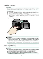
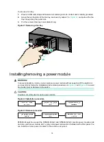
Installing/removing a fan tray
CAUTION:
•
Install two fan trays of the same model on the switch. Do not power on the switch when it does
not have fan trays or has only one fan tray installed.
•
Do not leave any slots empty when the switch is operating. Install a module or filler panel in the
slots.
•
If both fan trays fail while the switch is operating, replace them within 2 minutes while the switch
is operating.
•
If one fan tray fails while the switch is operating, perform either of the following tasks:
{
If the ambient temperature is not higher than 27°C (80.6°F), replace the fan tray within 24 hours and
make sure the failed fan tray is in position before the replacement.
{
If the ambient temperature is higher than 27°C (80.6°F), replace the fan tray immediately.
•
If you power cycle the switch after a fan tray fails, the switch will fail to start up.
S5560X-EI switches except the S5560X-34S-EI and S5560X-54S-EI provides fan tray slots and
support hot swapping of fan trays.
The switch comes with empty fan tray slots. Choose fan tray models for the switch based on the
ventilation requirement of the site. The air flow direction varies by fan tray model.
•
The LSPM1FANSA fan tray draws ambient air into the chassis from the power module side and
exhausts the air through the port side and chassis sides. The fan tray handle is blue.
•
The LSPM1FANSB fan tray draws ambient air into the chassis from the port side and chassis
sides and exhausts the air through the power module side. The fan tray handle is red.
For information about the fan trays available for the switch, see "
Appendix B FRUs and compatibility
6
5
1
2
3
4


