background image


H3C S5820X&S5800 Series Ethernet Switches

Layer 3 - IP Services

Configuration Guide

Hangzhou H3C Technologies Co., Ltd. 

http://www.h3c.com 


Document Version:


6W103-20100716  

Product Version:


Release 1110 


Summary of Contents for s5820x series

Page 1: ...H3C S5820X S5800 Series Ethernet Switches Layer 3 IP Services Configuration Guide Hangzhou H3C Technologies Co Ltd http www h3c com Document Version 6W103 20100716 Product Version Release 1110...

Page 2: ...ware Secware Storware NQA VVG V2 G Vn G PSPT XGbus N Bus TiGem InnoVision and HUASAN are trademarks of Hangzhou H3C Technologies Co Ltd All other trademarks that may be mentioned in this manual are th...

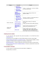
Page 3: ...ace includes z Audience z Document Organization z Conventions z About the H3C S5800 S5820X Documentation Set z Obtaining Documentation z Documentation Feedback Audience This documentation set is inten...

Page 4: ...r keyword and argument combination before the ampersand sign can be entered 1 to n times A line that starts with a pound sign is comments Symbols Convention Description Means reader be extremely caref...

Page 5: ...llation and removal of the OAP cards available for the products H3C Low End Series Ethernet Switches Pluggable Modules Manual Describes the models appearances and specifications of the pluggable modul...

Page 6: ...ssword when the login password is lost Operations and maintenance Release notes Provide information about the product release including the version history hardware and software compatibility matrix v...

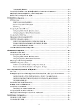
Page 7: ...nfiguration 2 1 Proxy ARP Overview 2 1 Proxy ARP 2 1 Local Proxy ARP 2 2 Enabling Proxy ARP 2 2 Displaying and Maintaining Proxy ARP 2 3 Proxy ARP Configuration Examples 2 3 Proxy ARP Configuration Ex...

Page 8: ...ynamic Address Allocation for an Extended Address Pool 6 7 Configuring a Domain Name Suffix for the Client 6 8 Configuring DNS Servers for the Client 6 9 Configuring WINS Servers and NetBIOS Node Type...

Page 9: ...7 10 DHCP Relay Agent Configuration Example 7 10 DHCP Relay Agent Option 82 Support Configuration Example 7 11 Troubleshooting DHCP Relay Agent Configuration 7 12 8 DHCP Client Configuration 8 1 Intro...

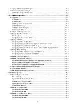
Page 10: ...IPv6 DNS 12 1 Configuring the IPv6 DNS Client 12 1 Configuring Static Domain Name Resolution 12 1 Configuring Dynamic Domain Name Resolution 12 1 Displaying and Maintaining IPv6 DNS 12 2 IPv6 DNS Con...

Page 11: ...guring PMTU Discovery 15 19 Configuring a Static PMTU for a Specified IPv6 Address 15 19 Configuring the Aging Time for Dynamic PMTUs 15 19 Configuring IPv6 TCP Properties 15 19 Configuring ICMPv6 Pac...

Page 12: ...quisites 17 10 Configuration Procedure 17 10 Configuration Example 17 12 Configuring a 6to4 Tunnel 17 15 Configuration Prerequisites 17 15 Configuration Procedure 17 15 6to4 Tunnel Configuration Examp...

Page 13: ...ng a GRE over IPv6 Tunnel 17 41 Configuration Prerequisites 17 41 Configuration Procedure 17 41 Configuration Example 17 42 Displaying and Maintaining Tunneling Configuration 17 45 Troubleshooting Tun...

Page 14: ...ormat of the ARP request reply Figure 1 1 ARP message format The following describe the fields in Figure 1 1 z Hardware type This field specifies the hardware address type The value 1 represents Ether...

Page 15: ...address and the MAC address of Host A respectively and the target IP address and the target MAC address are the IP address of Host B and an all zero MAC address respectively Because the ARP request is...

Page 16: ...not modify the IP to MAC mapping Thus communications between devices are protected Static ARP entries can be classified into long and short z A long static ARP entry can be directly used to forward pa...

Page 17: ...RP entry arp static ip address mac address vpn instance vpn instance name Required No short static ARP entry is configured by default z The vlan id argument must be the ID of an existing VLAN that cor...

Page 18: ...to the actual network condition Follow these steps to set the aging time for dynamic ARP entries To do Use the command Remarks Enter system view system view Set the aging time for dynamic ARP entries...

Page 19: ...o the hosts on a network the traffic destined for the gateway from the hosts is sent to the attacker instead As a result the hosts cannot access the external network To prevent such gateway spoofing a...

Page 20: ...kets upon receiving ARP requests from another network segment Enter interface view interface interface type interface number Enable periodic sending of gratuitous ARP packets and set the sending inter...

Page 21: ...ude regular expression count Available in any view Display the aging time for dynamic ARP entries display arp timer aging Available in any view Clear ARP entries from the ARP table reset arp all dynam...

Page 22: ...N interace 10 and configure its IP address Switch interface vlan interface 10 Switch vlan interface10 ip address 192 168 1 2 8 Switch vlan interface10 quit Configure a static ARP entry with IP address...

Page 23: ...cation between the two hosts This is achieved by proxy ARP which hides the physical details of the network Proxy ARP involves common proxy ARP and local proxy ARP which are described in the following...

Page 24: ...default gateway or do not have routing capability Local Proxy ARP As shown in Figure 2 2 Host A and Host B belong to VLAN 2 but are isolated at Layer 2 Host A connects to GigabitEthernet1 0 3 while Ho...

Page 25: ...e interface type interface number Available in any view Display whether local proxy ARP is enabled display local proxy arp interface interface type interface number Available in any view Proxy ARP Con...

Page 26: ...address 192 168 20 99 255 255 255 0 Enable proxy ARP on interface VLAN interface 2 Switch Vlan interface2 proxy arp enable After completing preceding configurations use the ping command to verify the...

Page 27: ...tchB GigabitEthernet1 0 2 quit SwitchB interface gigabitethernet 1 0 3 SwitchB GigabitEthernet1 0 3 port isolate enable SwitchB GigabitEthernet1 0 3 quit 2 Configure Switch A Create VLAN 2 and add gig...

Page 28: ...16 GE1 0 1 VLAN 5 Isolate uer vlan 5 Secondary VLAN 2 3 Configuration procedure 1 Configure Switch B Create VLAN 2 VLAN 3 and VLAN 5 on Switch B Add GigabitEthernet1 0 2 to VLAN 2 GigabitEthernet1 0 3...

Page 29: ...5 255 0 0 The ping operation from Host A to Host B is unsuccessful because they are isolated at Layer 2 Configure local proxy ARP to implement Layer 3 communication between VLAN 2 and VLAN 3 SwtichA V...

Page 30: ...ry are 25 minutes and 15 minutes respectively If an ARP snooping entry is not updated within 15 minutes it becomes invalid and cannot be used After that if an ARP packet whose source IP and MAC addres...

Page 31: ...Snooping To do Use the command Remarks Display ARP snooping entries display arp snooping ip ip address vlan vlan id Available in any view Remove ARP snooping entries reset arp snooping ip ip address v...

Page 32: ...eneral IP addresses are written in dotted decimal notation for example 10 1 1 1 Each IP address has two parts z Net ID Identifies a network z Host id Identifies a host on a network IP addresses are di...

Page 33: ...fies a host on the local network For example IP address 0 0 0 16 indicates the host with a host ID of 16 on the local network z An IP address with an all zero host ID Identifies a network z An IP addr...

Page 34: ...faces to obtain IP addresses through BOOTP and DHCP A newly configured IP address overwrites the previous one This chapter only covers how to assign IP addresses manually For how to obtain IP addresse...

Page 35: ...secondary IP addresses assigned to an interface can be located on the same network segment but the IP addresses of different interfaces must be on different network segments IP Addressing Configurati...

Page 36: ...16 1 2 bytes 56 Sequence 1 ttl 255 time 25 ms Reply from 172 16 1 2 bytes 56 Sequence 2 ttl 255 time 27 ms Reply from 172 16 1 2 bytes 56 Sequence 3 ttl 255 time 26 ms Reply from 172 16 1 2 bytes 56...

Page 37: ...n communicate with the hosts on subnet 172 16 2 0 24 Ping a host on subnet 172 16 1 0 24 from a host on subnet 172 16 2 0 24 to check the connectivity Host B can be successfully pinged from Host A Dis...

Page 38: ...then the server returns a reply to send configuration parameters such as an IP address to the client A typical DHCP application as shown in Figure 5 1 includes a DHCP server and multiple clients PCs...

Page 39: ...CP servers send offers to the client the client accepts the first received offer and broadcasts it in a DHCP REQUEST message to formally request the IP address 4 All DHCP servers receive the DHCP REQU...

Page 40: ...ight types These types of messages have the same format except that some fields have different values The numbers in parentheses indicate the size of each field in bytes Figure 5 3 DHCP message format...

Page 41: ...5 4 DHCP option format Introduction to DHCP Options The common DHCP options are as follows z Option 3 Router option It specifies the gateway address to be assigned to the client z Option 6 DNS server...

Page 42: ...er identifier acquired by the customer premises equipment CPE from the DHCP server and sent to the ACS for selecting vender specific configurations and parameters z Preboot Execution Environment PXE s...

Page 43: ...te the DHCP client to further implement security control and accounting The Option 82 supporting server can also use such information to define individual assignment policies of IP address and other p...

Page 44: ...interface that received the client s request Its format is shown in Figure 5 10 Figure 5 10 Sub option 1 in verbose padding format In Figure 5 10 except that the VLAN ID field has a fixed length of 2...

Page 45: ...ients take this ID as the voice VLAN or not z Sub option 4 Failover route that specifies the destination IP address and the called number that a SIP user uses to reach another SIP user when both the p...

Page 46: ...nfiguration Examples z Troubleshooting DHCP Server Configuration The DHCP server configuration is supported only on VLAN interfaces and loopback interfaces The secondary IP address pool configuration...

Page 47: ...ool for natural networks branches are address pools for subnets and leaves are addresses statically bound to clients For the same level address pools a previously configured pool has a higher selectio...

Page 48: ...ols 1 1 1 0 24 and 1 1 1 0 25 are configured on the DHCP server If the IP address of the interface receiving DHCP requests is 1 1 1 1 25 the DHCP server will select IP addresses for clients from addre...

Page 49: ...address pool Task Remarks Creating a DHCP Address Pool Required Configuring manual address allocation Configuring an Address Allocation Mode for a Common Address Pool Configuring dynamic address alloc...

Page 50: ...Address Allocation Mode for a Common Address Pool You can configure either the static binding or dynamic address allocation for a common address pool as needed You must specify an address range for th...

Page 51: ...overwrite the previous one z The IP address of the static binding cannot be an interface address of the DHCP server Otherwise an IP address conflict may occur and the bound client cannot obtain an IP...

Page 52: ...ew using the network command repeatedly overwrites the previous configuration z After you exclude IP addresses from automatic allocation using the dhcp server forbidden ip command neither a common add...

Page 53: ...ip command in DHCP address pool view are not assignable in the current extended address pool but are assignable in other address pools Configuring a Domain Name Suffix for the Client You can specify a...

Page 54: ...lient to approach name resolution There are four NetBIOS node types z b broadcast node The b node client sends the destination name in a broadcast message The destination returns its IP address to the...

Page 55: ...command Remarks Enter system view system view Enter DHCP address pool view dhcp server ip pool pool name extended Specify the BIMS server IP address port number and shared key bims server ip ip addres...

Page 56: ...y default Configure the voice VLAN voice config voice vlan vlan id disable enable Optional Not configured by default Specify the failover IP address and dialer string voice config fail over ip address...

Page 57: ...ver ip address ip address Specify the name of the TFTP server tftp server domain name domain name Required to use either command Not specified by default Specify the bootfile name bootfile name bootfi...

Page 58: ...15 Domain Name domain name ascii 44 NetBIOS over TCP IP Name Server Option nbns list ip address 46 NetBIOS over TCP IP Node Type Option netbios type hex 66 TFTP server name tftp server ascii 67 Bootf...

Page 59: ...pool containing the secondary IP address of the server interface connected to the client if the interface has multiple secondary IP addresses the address pool containing the first secondary IP addres...

Page 60: ...this configuration complete the following configurations on the DHCP server z Enable DHCP z Configure the DHCP address pool Enabling Unauthorized DHCP Server Detection Unauthorized DHCP servers may e...

Page 61: ...teps to configure IP address conflict detection To do Use the command Remarks Enter system view system view Specify the number of ping packets dhcp server ping packets number Optional One ping packet...

Page 62: ...ed all ip ip address pool pool name Available in any view Display information about assignable IP addresses display dhcp server free ip Available in any view Display IP addresses excluded from automat...

Page 63: ...t are not on the same subnet and they communicate with each other via a DHCP relay agent The DHCP server configuration for the two types is the same Static IP Address Assignment Configuration Example...

Page 64: ...SwitchA dhcp pool 1 dns list 10 1 1 2 SwitchA dhcp pool 1 gateway list 10 1 1 126 3 Verification After the preceding configuration is complete Switch B can obtain IP address 10 1 1 5 and other networ...

Page 65: ...omitted 2 Configure the DHCP server Enable DHCP SwitchA system view SwitchA dhcp enable Enable the DHCP server on VLAN interface 1 SwitchA interface vlan interface 1 SwitchA Vlan interface1 dhcp selec...

Page 66: ...ay dhcp server ip in use command on the DHCP server to view the IP addresses assigned to the clients Self Defined Option Configuration Example Network requirements As shown in Figure 6 3 the DHCP clie...

Page 67: ...d to the clients Troubleshooting DHCP Server Configuration Symptom A client s IP address obtained from the DHCP server conflicts with another IP address Analysis A host on the subnet may have the same...

Page 68: ...h subnet which is not practical DHCP relay agent solves the problem Via a relay agent DHCP clients communicate with a DHCP server on another subnet to obtain configuration parameters Thus DHCP clients...

Page 69: ...ts IP address and forwards the message to the designated DHCP server in unicast mode 2 Based on the giaddr field the DHCP server returns an IP address and other configuration parameters to the relay a...

Page 70: ...d Option 82 normal Forward the message after adding the Option 82 padded in normal format verbose Forward the message after adding the Option 82 padded in verbose format no Option 82 user defined Forw...

Page 71: ...ype interface number Enable the DHCP relay agent on the current interface dhcp select relay Required With DHCP enabled interfaces work in the DHCP server mode If the DHCP client obtains an IP address...

Page 72: ...server group does not exist the interface still uses the previous correlation z The group id argument in the dhcp relay server select command is configure by using the dhcp relay server group command...

Page 73: ...guring periodic refresh of dynamic client entries Via the DHCP relay agent a DHCP client unicasts a DHCP RELEASE message to the DHCP server when releasing its dynamically obtained IP address If the DH...

Page 74: ...tion To do Use the command Remarks Enter system view system view Enable unauthorized DHCP server detection dhcp relay server detect Required Disabled by default The device stores information about det...

Page 75: ...view Enter interface view interface interface type interface number Enable the relay agent to support Option 82 dhcp relay information enable Required Disabled by default Configure the handling strat...

Page 76: ...u must perform related configuration on both the DHCP server and relay agent z If the handling strategy of the DHCP relay agent is configured as replace you need to configure a padding format for Opti...

Page 77: ...agent reset dhcp relay statistics server group group id Available in user view DHCP Relay Agent Configuration Examples DHCP Relay Agent Configuration Example Network requirements As shown in Figure 7...

Page 78: ...n the DHCP server is also required to guarantee the client server communication via the relay agent z Because the DHCP relay agent and server are on different subnets you need to configure a static ro...

Page 79: ...gurations function normally Troubleshooting DHCP Relay Agent Configuration Symptom DHCP clients cannot obtain any configuration parameters via the DHCP relay agent Analysis Some problems may occur wit...

Page 80: ...P server cannot be a Windows 2000 Server or Windows 2003 Server Introduction to DHCP Client With the DHCP client enabled an interface will use DHCP to obtain configuration parameters such as an IP add...

Page 81: ...the command Remarks Display specified configuration information display dhcp client verbose interface interface type interface number Available in any view DHCP Client Configuration Example Network r...

Page 82: ...l 0 network 10 1 1 0 mask 255 255 255 0 SwitchA dhcp pool 0 expired day 10 SwitchA dhcp pool 0 dns list 20 1 1 1 SwitchA dhcp pool 0 option 121 hex 18 14 01 01 0A 01 01 02 2 Configure Switch B Enable...

Page 83: ...o view the route information on Switch B A static route to network 20 1 1 0 24 is added to the routing table SwitchB Vlan interface2 display ip routing table Routing Tables Public Destinations 5 Route...

Page 84: ...ervers If there is an unauthorized DHCP server on a network DHCP clients may obtain invalid IP addresses and network configuration parameters and cannot normally communicate with other network devices...

Page 85: ...y Configuration Guide z VLAN mapping The device replaces service provider VLANs SVLANs in packets with customer VLANs CVLANs by searching corresponding DHCP snooping entries for DHCP client informatio...

Page 86: ...gabitEthernet1 0 3 and GigabitEthernet 1 0 4 GigabitEthernet 1 0 2 DHCP Snooping Support for Option 82 Option 82 records the location information of the DHCP client The administrator can locate the DH...

Page 87: ...replacing the original Option 82 with the user defined Option 82 normal Forward the message after adding the Option 82 padded in normal format verbose Forward the message after adding the Option 82 p...

Page 88: ...z If a Layer 2 Ethernet interface is added to an aggregation group the DHCP snooping configuration of the interface will not take effect After the interface quits the aggregation group the configurati...

Page 89: ...de type This code type configuration applies to non user defined Option 82 only Configure non user defined Option 82 Configure the code type for the remote ID sub option dhcp snooping information remo...

Page 90: ...is padded with the device name sysname of a node the device name must contain no spaces Otherwise the DHCP snooping enabled device will drop the message Displaying and Maintaining DHCP Snooping To do...

Page 91: ...SwitchB interface GigabitEthernet 1 0 1 SwitchB GigabitEthernet1 0 1 dhcp snooping trust SwitchB GigabitEthernet1 0 1 quit DHCP Snooping Option 82 Support Configuration Example Network requirements z...

Page 92: ...snooping information circuit id string company001 SwitchB GigabitEthernet1 0 2 dhcp snooping information remote id string device001 SwitchB GigabitEthernet1 0 2 quit Configure GigabitEthernet 1 3 to...

Page 93: ...a BOOTP client the interface can use BOOTP to get information such as IP address from the BOOTP server which simplifies your configuration Before using BOOTP an administrator needs to configure a BOOT...

Page 94: ...ient 3 The BOOTP client obtains the IP address from the received response Protocols and Standards Some protocols and standards related to BOOTP include z RFC 951 Bootstrap Protocol BOOTP z RFC 2132 DH...

Page 95: ...ss from the DHCP server by using BOOTP Figure 10 1 DHCP network diagram Configuration procedure The following describes only the configuration on Switch B serving as a client Configure VLAN interface...

Page 96: ...IP address mappings are stored in the local static name resolution table to improve efficiency Static Domain Name Resolution Static domain name resolution uses static mappings to translate from domain...

Page 97: ...For example a user can configure com as the suffix for aabbcc com The user only needs to type aabbcc to get the IP address of aabbcc com The resolver can add the suffix and delimiter before passing t...

Page 98: ...y as the DNS server and sends a DNS request to the DNS proxy that is the destination address of the request is the IP address of the DNS proxy 2 The DNS proxy searches the local static domain name res...

Page 99: ...previous one if there is any z You may create up to 50 static mappings between domain names and IPv4 addresses Configuring Dynamic Domain Name Resolution To send DNS queries to a correct server for r...

Page 100: ...ion table display ip host Available in any view Display IPv4 DNS server information display dns server dynamic Available in any view Display DNS suffixes display dns domain dynamic Available in any vi...

Page 101: ...8 time 3 ms Reply from 10 1 1 2 bytes 56 Sequence 4 ttl 128 time 2 ms Reply from 10 1 1 2 bytes 56 Sequence 5 ttl 128 time 3 ms host com ping statistics 5 packet s transmitted 5 packet s received 0 00...

Page 102: ...uration may vary with different DNS servers The following configuration is performed on a Windows server 2000 PC 1 Configure the DNS server Enter the DNS server configuration page Select Start Program...

Page 103: ...zone com and then select New Host to bring up a dialog box as shown in Figure 11 7 Enter host name host and IP address 3 1 1 1 Figure 11 7 Add a mapping between domain name and IP address 2 Configure...

Page 104: ...rom 3 1 1 1 bytes 56 Sequence 1 ttl 126 time 3 ms Reply from 3 1 1 1 bytes 56 Sequence 2 ttl 126 time 1 ms Reply from 3 1 1 1 bytes 56 Sequence 3 ttl 126 time 1 ms Reply from 3 1 1 1 bytes 56 Sequence...

Page 105: ...on function SwitchB system view SwitchB dns resolve Specify the DNS server 2 1 1 2 SwitchB dns server 2 1 1 2 4 Configuration verification Execute the ping host com command on switch B to verify that...

Page 106: ...ed domain name is in the cache z If the specified domain name does not exist check that dynamic domain name resolution is enabled and the DNS client can communicate with the DNS server z If the specif...

Page 107: ...configure static domain name resolution To do Use the command Remarks Enter system view system view Configure a mapping between a host name and an IPv6 address ipv6 host hostname ipv6 address Require...

Page 108: ...d dns domain commands are the same as those of IPv4 DNS z You can configure up to six DNS servers including those with IPv4 addresses z You can specify up to ten DNS suffixes Displaying and Maintainin...

Page 109: ...ame resolution to resolve domain name host com into IPv6 address 1 2 Switch ping ipv6 host com PING host com 1 2 56 data bytes press CTRL_C to break Reply from 1 2 bytes 56 Sequence 1 hop limit 128 ti...

Page 110: ...t the switch and the host are accessible to each another via available routes and the IPv6 addresses of the interfaces are configured as shown Figure 12 2 z This configuration may vary with different...

Page 111: ...ookup Zones select New zone and then follow the instructions to create a new zone named com Figure 12 3 Create a zone Create a mapping between the host name and the IPv6 address As shown in Figure 12...

Page 112: ...w Records to bring up a dialog box as shown in Figure 12 5 Select IPv6 Host AAA as the resource record type Figure 12 5 Select the resource record type As shown in Figure 12 6 type host name host and...

Page 113: ...3 Configuration verification Use the ping ipv6 host command on the switch to verify that the communication between the switch and the host is normal and that the corresponding destination IP address...

Page 114: ...e 1 ms Reply from 1 1 bytes 56 Sequence 4 hop limit 126 time 1 ms Reply from 1 1 bytes 56 Sequence 5 hop limit 126 time 1 ms host com ping statistics 5 packet s transmitted 5 packet s received 0 00 pa...

Page 115: ...the network ID identifies the target network and the host ID comprises all ones If a device is allowed to forward directed broadcasts to a directly connected network hackers may mount attacks to that...

Page 116: ...terface and VLAN interface 3 of Switch A are on the same network segment 1 1 1 0 24 VLAN interface 2 of Switch A and VLAN interface 2 of Switch B are on another network segment 2 2 2 0 24 The default...

Page 117: ...Enter system view system view Enable cut through forwarding cut through enable Required Disabled by default Currently the S5820X series support only this feature Enabling the SYN Cookie Feature As a...

Page 118: ...the MSS instead of the window s zoom factor and timestamp is negotiated during TCP connection establishment Configuring TCP Attributes Configuring TCP Optional Parameters TCP optional parameters that...

Page 119: ...its routing table after startup The default gateway will send ICMP redirect packets to the source host telling it to reselect a correct next hop to send the subsequent packets if the following conditi...

Page 120: ...ller than the packet to be forwarded but the packet has been set Don t Fragment the device sends the source a fragmentation needed and Don t Fragment DF set ICMP error packet Disadvantages of sending...

Page 121: ...ay ICMP statistics display icmp statistics slot slot number Available in any view Display socket information display ip socket socktype sock type task id socket id slot slot number Available in any vi...

Page 122: ...elper function to relay specified UDP packets In other words UDP Helper functions as a relay agent that converts broadcast packets into unicast packets and forwards them to a specified destination ser...

Page 123: ...be set to 67 or 68 z You can specify a port number or the corresponding parameter for an UDP port to forward packets For example udp helper port 53 and udp helper port dns specify the same UDP port nu...

Page 124: ...r UDP Helper configuration Configuration procedure The following configuration assumes that a route from Switch A to the network segment 10 2 0 0 16 is available Enable UDP Helper SwitchA system view...

Page 125: ...IPv4 The significant difference between IPv6 and IPv4 is that IPv6 increases the IP address size from 32 bits to 128 bits This section covers the following z IPv6 Features z IPv6 Addresses z IPv6 Nei...

Page 126: ...generate an IPv6 address and other configuration information automatically by using its link layer address and the prefix information advertised by a router To communicate with other hosts on the same...

Page 127: ...876A 130B A double colon may appear once or not at all in an IPv6 address Otherwise the device cannot determine how many zeros the double colons represent when converting them to zeros to restore a 1...

Page 128: ...addresses Unicast addresses Unicast addresses comprise global unicast addresses link local unicast addresses site local unicast addresses the loopback address and the unspecified address z The global...

Page 129: ...esponding solicited node address The format of a solicited node multicast address is FF02 0 0 0 0 1 FFXX XXXX Where FF02 0 0 0 0 1 FF is fixed and consists of 104 bits and XX XXXX is the last 24 bits...

Page 130: ...Neighbor Discovery Protocol The IPv6 Neighbor Discovery Protocol NDP uses five types of ICMPv6 messages to implement the following functions z Address resolution z Neighbor reachability detection z D...

Page 131: ...on address is the solicited node multicast address of Host B The NS message contains the link layer address of Host A 2 After receiving the NS message Host B judges whether the destination address of...

Page 132: ...and address autoconfiguration Router prefix discovery enables a node to locate the neighboring routers and to learn from the received RA message configuration parameters such as the prefix of the netw...

Page 133: ...e receiving interface is the forwarding interface z The selected route itself is not created or modified by an ICMPv6 Redirect message z The selected route is not the default route z The IPv6 packet t...

Page 134: ...application that supports both IPv4 and IPv6 either TCP or UDP can be selected at the transport layer whereas the IPv6 stack is preferred at the network layer Dual stack is suitable for communication...

Page 135: ...hitecture IPv6 Basics Configuration Task List Complete the following tasks to perform IPv6 basics configuration Task Remarks Configuring Basic IPv6 Functions Required Configuring IPv6 NDP Optional Con...

Page 136: ...resses can be assigned manually To avoid link local address conflicts it is recommended to use the automatic generation method Follow these steps to configure an IPv6 unicast address To do Use the com...

Page 137: ...u delete the manually assigned address the automatically generated link local address is validated z The undo ipv6 address auto link local command can only remove the link local addresses generated th...

Page 138: ...entry for a VLAN interface z After a static neighbor entry is configured by using the first method the device needs to resolve the corresponding Layer 2 port information of the VLAN interface z If you...

Page 139: ...gurable parameters in an RA message and their descriptions Table 15 4 Parameters in an RA message and their descriptions Parameters Description Cur Hop Limit When sending an IPv6 packet a host uses th...

Page 140: ...device retransmits the NS message Reachable Time If the neighbor reachability detection shows that a neighbor is reachable the device considers the neighbor reachable within the specified reachable ti...

Page 141: ...A messages ipv6 nd ra prefix ipv6 address prefix length ipv6 address prefix length valid lifetime preferred lifetime no autoconfig off link Optional By default no prefix information is configured for...

Page 142: ...In VRRP networking the source MAC address in an NA message is always different from that in the link layer address option at present and therefore the consistency check on the MAC address of ND packet...

Page 143: ...Use the command Remarks Enter system view system view Configure a static PMTU for a specified IPv6 address ipv6 pathmtu ipv6 address value Required By default no static PMTU is configured Configuring...

Page 144: ...t the size of the IPv6 TCP sending receiving buffer tcp ipv6 window size Optional 8 KB by default Configuring ICMPv6 Packet Sending Configuring the Maximum ICMPv6 Error Packets Sent in an Interval If...

Page 145: ...lticast echo requests Follow these steps to enable replying to multicast echo requests To do Use the command Remarks Enter system view system view Enable replying to multicast echo requests ipv6 icmpv...

Page 146: ...view Display the total number of neighbor entries satisfying the specified conditions display ipv6 neighbors all dynamic static slot slot number interface interface type interface number vlan vlan id...

Page 147: ...6 Configuration Example Network requirements z Host Switch A and Switch B are connected through Ethernet ports Add the Ethernet ports into corresponding VLANs configure IPv6 addresses for the VLAN int...

Page 148: ...chB ipv6 route static 2001 64 3001 1 z Configure Host Enable IPv6 for Host to automatically get an IPv6 address through IPv6 NDP SwitchA Vlan interface1 display ipv6 neighbors interface GigabitEtherne...

Page 149: ...drErrors 0 InDiscards 0 OutDiscards 0 SwitchA Vlan interface1 display ipv6 interface vlan interface 1 verbose Vlan interface1 current state UP Line protocol current state UP IPv6 is enabled link local...

Page 150: ...the IPv6 global unicast addresses configured on the interface are displayed SwitchB display ipv6 interface vlan interface 2 verbose Vlan interface2 current state UP Line protocol current state UP IPv...

Page 151: ...ing a link local address you should use the i parameter to specify an interface for the link local address SwitchB ping ipv6 c 1 3001 1 PING 3001 1 56 data bytes press CTRL_C to break Reply from 3001...

Page 152: ...Solution z Use the display current configuration command in any view or the display this command in system view to verify that IPv6 is enabled z Use the display ipv6 interface command in any view to v...

Page 153: ...ement z Assign configuration parameters to hosts such as a DNS server address and domain name Basic Concepts Multicast address for all DHCPv6 servers and relay agents The multicast address FF02 1 2 id...

Page 154: ...n instead of stateful DHCPv6 configuration that is the device can only obtain other network configuration parameters instead of an IPv6 address from the DHCPv6 server Stateless DHCPv6 Configuration Af...

Page 155: ...at the client requests from the DHCPv6 server 2 After receiving the information request message the DHCPv6 server returns a reply message containing the requested configuration parameters to the clien...

Page 156: ...other network parameters assigned by the DHCPv6 server to perform network configuration Protocols and Standards z RFC 3736 Stateless Dynamic Host Configuration Protocol DHCP Service for IPv6 z RFC 33...

Page 157: ...that operates as a DHCPv6 relay agent encapsulates the request into a Relay forward message and forwards the message to the specified DHCPv6 server which then assigns an IPv6 address and other configu...

Page 158: ...and DHCPv6 relay agent at the same time Displaying and Maintaining DHCPv6 To do Use the command Remarks Display DHCPv6 client information display ipv6 dhcp client interface interface type interface n...

Page 159: ...messages SwitchB Vlan interface2 undo ipv6 nd ra halt 2 Configure Switch A Enable the IPv6 packet forwarding function SwitchA system view SwitchA ipv6 Enable stateless IPv6 address autoconfiguration o...

Page 160: ...Vlan interface2 Packets Received 1 Reply 1 Advertise 0 Reconfigure 0 Invalid 0 Packets Sent 5 Solicit 0 Request 0 Confirm 0 Renew 0 Rebind 0 Information request 5 Release 0 Decline 0 DHCPv6 Relay Age...

Page 161: ...messages and set the M and O flags SwitchA Vlan interface1 undo ipv6 nd ra halt SwitchA Vlan interface1 ipv6 nd autoconfig managed address flag SwitchA Vlan interface1 ipv6 nd autoconfig other flag 3...

Page 162: ...r network protocol and transfer them over the network A tunnel is a virtual point to point connection providing a channel to transfer encapsulated packets Packets are encapsulated and decapsulated at...

Page 163: ...Pv6 is compatible with all protocols except IPv4 in the TCP IP suite Therefore IPv6 can completely take the place of IPv4 Before IPv6 becomes the dominant protocol networks using the IPv6 protocol sta...

Page 164: ...packet according to the destination address in the decapsulated IPv6 packet If the destination address is the device itself the device forwards the IPv6 packet to the upper layer protocol for process...

Page 165: ...are mainly used to provide stable connections for regular secure communication between border routers or between border routers and hosts for access to remote IPv6 networks 2 6to4 tunnel An automatic...

Page 166: ...efgh which need not be globally unique Through the embedded IPv4 address an ISATAP tunnel can automatically be created to transfer IPv6 packets The ISATAP tunnel is mainly used for connection between...

Page 167: ...eling protocol The IPv4 IPv6 over IPv6 tunneling protocol RFC 2473 is developed for IPv4 or IPv6 data packet encapsulation so that encapsulated packets can be transmitted over an IPv6 network The enca...

Page 168: ...rough the GRE tunnel The following takes the network shown in Figure 17 5 as an example to describe how an X protocol packet traverses the IP network through a GRE tunnel Encapsulation process 1 After...

Page 169: ...face Router B checks the destination address 2 If the destination is itself Router B strips off the IP header of the packet and submits the resulting packet to the GRE protocol 3 The GRE protocol chec...

Page 170: ...its service type of tunnel and add the unused Layer 2 Ethernet interfaces on the switches into the group For more information about the service loopback group see Service Loopback Group Configuration...

Page 171: ...such as the VLAN interface and loopback interface on the device to ensure normal communication z Specify one of the above interfaces as the source interface of the tunnel z Ensure reachability between...

Page 172: ...ess or interface is configured for the tunnel Configure a destination address for the tunnel destination ip address Required By default no destination address is configured for the tunnel z After a tu...

Page 173: ...figure an IPv4 address for VLAN interface 100 SwitchA interface vlan interface 100 SwitchA Vlan interface100 ip address 192 168 100 1 255 255 255 0 SwitchA Vlan interface100 quit Configure an IPv6 add...

Page 174: ...uit Configure an IPv6 manual tunnel SwitchB interface tunnel 0 SwitchB Tunnel0 ipv6 address 3001 2 64 SwitchB Tunnel0 source vlan interface 100 SwitchB Tunnel0 destination 192 168 100 1 SwitchB Tunnel...

Page 175: ...address es 3001 2 subnet is 3001 64 Joined group address es FF02 1 FF00 0 FF02 1 FF00 1 FF02 1 FFA8 3201 FF02 2 FF02 1 MTU is 1480 bytes ND reachable time is 30000 milliseconds ND retransmit interval...

Page 176: ...terface view interface tunnel number ipv6 address ipv6 address prefix length ipv6 address prefix length Configure an IPv6 global unicast address or a site local address ipv6 address ipv6 address prefi...

Page 177: ...guration see IPv6 Static Routing Configuration or other routing protocol configurations in the Layer 3 IP Routing Configuration Guide z The automatic tunnel interfaces using the same encapsulation pro...

Page 178: ...interface 101 SwitchA interface vlan interface 101 SwitchA Vlan interface101 ipv6 address 2002 0201 0101 1 1 64 SwitchA Vlan interface101 quit Configure a 6to4 tunnel SwitchA interface tunnel 0 Switc...

Page 179: ...002 0501 0101 1 64 SwitchB Tunnel0 source vlan interface 100 SwitchB Tunnel0 tunnel protocol ipv6 ipv4 6to4 SwitchB Tunnel0 quit Create service loopback group 1 to support the tunnel service SwitchB s...

Page 180: ...onfiguration Procedure Follow these steps to configure an ISATAP tunnel To do Use the command Remarks Enter system view system view Enable IPv6 ipv6 Required By default the IPv6 forwarding function is...

Page 181: ...esides you need to configure a static route or dynamic routing for forwarding those packets through this tunnel interface Because automatic tunnels do not support dynamic routing you can configure a s...

Page 182: ...1 255 0 0 0 Switch Vlan interface101 quit Configure an ISATAP tunnel Switch interface tunnel 0 Switch Tunnel0 ipv6 address 2001 5efe 0101 0101 64 Switch Tunnel0 source vlan interface 101 Switch Tunne...

Page 183: ...dded IPv4 address 0 0 0 0 router link layer address 0 0 0 0 preferred link local fe80 5efe 2 1 1 2 life infinite link MTU 1280 true link MTU 65515 current hop limit 128 reachable time 42500ms base 300...

Page 184: ...t 0 0 loss Approximate round trip times in milli seconds Minimum 1ms Maximum 1ms Average 1ms Configuration verification After the above configurations the ISATAP host can access the host in the IPV6 n...

Page 185: ...tunnel interface as the outbound interface or the peer tunnel interface as the next hop A similar configuration needs to be performed at the other tunnel end If you configure dynamic routing at both e...

Page 186: ...interface101 quit Create the interface tunnel 1 SwitchA interface tunnel 1 Configure an IPv4 address for the interface tunnel 1 SwitchA Tunnel1 ip address 10 1 2 1 255 255 255 0 Configure the tunnel...

Page 187: ...figure the tunnel encapsulation mode SwitchB Tunnel2 tunnel protocol ipv4 ipv4 Configure the source address for the interface tunnel 2 IP address of VLAN interface 101 SwitchB Tunnel2 source 3 1 1 1 C...

Page 188: ...ncapsulation is TUNNEL service loopback group ID is 1 Tunnel source 3 1 1 1 destination 2 1 1 1 Tunnel protocol transport IP IP Last clearing of counters Never Last 300 seconds input 0 bytes sec 0 pac...

Page 189: ...el interface view interface tunnel number Configure an IPv4 address for the tunnel interface ip address ip address mask mask length sub Required By default no IPv4 address is configured for the tunnel...

Page 190: ...ing Configuration or other routing protocol configurations in the Layer 3 IP Routing Configuration Guide z Two or more tunnel interfaces using the same encapsulation protocol must have different sourc...

Page 191: ...002 2 1 SwitchA Tunnel1 quit Create service loopback group 1 to support the tunnel service SwitchA service loopback group 1 type tunnel Add GigabitEthernet 1 0 3 to service loopback group 1 SwitchA in...

Page 192: ...3 quit Reference service loopback group 1 on the tunnel SwitchB interface tunnel 2 SwitchB Tunnel2 service loopback group 1 SwitchB Tunnel2 quit Configure a static route from Switch B through the inte...

Page 193: ...me 15 ms Reply from 30 1 3 1 bytes 56 Sequence 3 ttl 255 time 16 ms Reply from 30 1 3 1 bytes 56 Sequence 4 ttl 255 time 15 ms Reply from 30 1 3 1 bytes 56 Sequence 5 ttl 255 time 16 ms 30 1 3 1 ping...

Page 194: ...ess is configured for the tunnel interface Specify the IPv6 over IPv6 tunnel mode tunnel protocol ipv6 ipv6 Optional By default the tunnel is a GRE over IPv4 tunnel The same tunnel mode should be conf...

Page 195: ...ng Configuration Guide z The IPv6 address and the destination address of a tunnel interface must not be in the same network segment z The destination address of a route with the tunnel interface as th...

Page 196: ...col ipv6 ipv6 Configure the source address for the interface tunnel 1 IP address of VLAN interface 101 SwitchA Tunnel1 source 2002 11 1 Configure the destination address for the interface tunnel 1 IP...

Page 197: ...nel2 destination 2002 11 1 SwitchB Tunnel2 quit Create service loopback group 1 to support the tunnel service SwitchB service loopback group 1 type tunnel Add GigabitEthernet 1 0 3 to service loopback...

Page 198: ...is 30000 milliseconds ND retransmit interval is 1000 milliseconds Hosts use stateless autoconfig for addresses IPv6 Packet statistics Ping the IPv6 address of the peer interface VLAN interface 100 fr...

Page 199: ...gth Required By default a tunnel interface has no IPv4 address Set the tunnel mode to GRE over IPv4 tunnel protocol gre Optional By default the tunnel is a GRE over IPv4 tunnel Note that you need to c...

Page 200: ...ress of the peer tunnel interface as its next hop Or you can enable a dynamic routing protocol on both the tunnel interface and the router interface connecting the private network Configuration Exampl...

Page 201: ...1 service loopback group 1 SwitchA Tunnel1 quit Configure a static route from Switch A through interface Tunnel 1 to Group 2 SwitchA ip route static 10 1 3 0 255 255 255 0 tunnel 1 2 Configure Switch...

Page 202: ...aces can serve as the source of a virtual tunnel interface to ensure the reachability of the destination address Configuration Procedure Follow these steps to configure a GRE over IPv6 tunnel To do Us...

Page 203: ...must be the destination address at the other end and vice versa z Tunnel interfaces using the same encapsulation protocol must have different source addresses and destination addresses z If you config...

Page 204: ...face101 ipv6 address 2002 1 1 64 SwitchA Vlan interface101 quit Create an interface named Tunnel 0 SwitchA interface tunnel 0 Configure an IPv4 address for interface Tunnel 0 SwitchA Tunnel0 ip addres...

Page 205: ...01 ipv6 address 2002 2 1 64 SwitchB Vlan interface101 quit Create an interface named Tunnel 0 SwitchB interface tunnel 0 Configure an IPv4 address for interface Tunnel 0 SwitchB Tunnel0 ip address 10...

Page 206: ...the configuration of related parameters such as tunnel source address tunnel destination address and tunnel mode the tunnel interface is still not up Solution Follow the steps below 1 The common cause...

Page 207: ...ing IP Address Conflict Detection 6 16 Configuring Option 184 Parameters for the Client with Voice Service 6 11 Configuring Parameters Related to RA Messages 15 15 Configuring Self Defined DHCP Option...

Page 208: ...o Requests 15 21 Enabling Sending of ICMPv6 Time Exceeded Messages 15 21 Enabling the ARP Entry Check1 5 Enabling the DHCP Relay Agent on an Interface 7 4 Enabling Unauthorized DHCP Server Detection 6...

Page 209: ...ynamic ARP Entries1 5 Special IP Addresses4 2 Stateless DHCPv6 Configuration Example 16 7 Stateless DHCPv6 Configuration 16 2 Static Domain Name Resolution 11 1 Static IP Address Assignment Configurat...

Reviews: