background image

H3C S5820X Series Ethernet Switches

Installation Manual


New H3C Technologies Co., Ltd.  
http://www.h3c.com.hk 
 
Document version: 6W110-20170718


Summary of Contents for s5820x series

Page 1: ...H3C S5820X Series Ethernet Switches Installation Manual New H3C Technologies Co Ltd http www h3c com hk Document version 6W110 20170718...

Page 2: ...her trademarks that may be mentioned in this manual are the property of their respective owners Notice The information in this document is subject to change without notice Every effort has been made i...

Page 3: ...enter literally as shown Italic Italic text represents arguments that you replace with actual values Square brackets enclose syntax choices keywords or arguments that are optional x y Braces enclose...

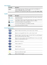
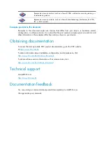
Page 4: ...ORTANT An alert that calls attention to essential information NOTE An alert that contains additional or supplementary information TIP An alert that provides helpful information Network topology icons...

Page 5: ...screenshots and other information in the examples differ from what you have on your device Obtaining documentation To access the most up to date H3C product documentation go to the H3C website at htt...

Page 6: ...r module status LEDs 11 Seven segment LED 11 Port mode LED 12 10 100 1000Base T Ethernet port LED 12 SFP port LED 13 Management Ethernet port LEDs 13 OAP card status LED 14 Hot swappable power modules...

Page 7: ...DC300 52 Installing Removing an interface card 52 Installing an interface card 52 Removing an interface card 53 Installing Removing an OAP card 54 Installing an OAP card in the OAP card slot 54 Removi...

Page 8: ...Troubleshooting the LSVM1AC650 LSVM1DC650 LSVM1AC300 LSVM1DC300 72 OAP card failure 72 Failure of the OAP card in the OAP card slot 72 Failure of the OAP card in an expansion interface card slot 73 F...

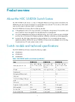
Page 9: ...H3C Open Application Architecture OAA You can install customized open application platform OAP cards in your S5820X switch to provide value added services including firewall anti virus IPS and wireles...

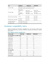
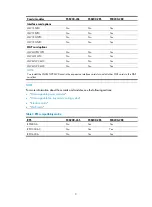
Page 10: ...45 C 32 F to 113 F Operating humidity 10 to 90 noncondensing Hardware compatibility matrix Interface cards OAP cards PoE modules swappable fan trays power modules and RPSs must be purchased separatel...

Page 11: ...20 No No Yes NOTE You install the LSWM1WCM20 card in the expansion interface card slot and all other OAP cards in the OAP card slot NOTE For more information about these cards and modules see the foll...

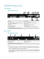
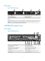
Page 12: ...Figure 2 S5820X 26S rear panel 1 Power module slot 1 2 Power module slot 2 3 Fan tray slot 1 4 Fan tray slot 2 5 Grounding screw auxiliary grounding point 2 NOTE The S5820X 26S switch comes with the...

Page 13: ...em status LED SYS 11 Power supply 1 status LED PWR1 12 Power supply 2 status LED PWR2 13 Port LED mode switching button 14 ACT LED for the management Ethernet port 15 LINK LED for the management Ether...

Page 14: ...eded In this figure two PSR300 12A AC power modules are installed in the slots S5820X 28C panel views Front panel Figure 6 S5820X 28C front panel 1 Expansion interface card slot 2 Seven segment LED 3...

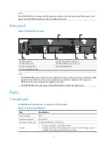
Page 15: ...covered by a filler panel You can install one or two power modules for your switch as needed In this figure two PSR300 12A AC power modules are installed in the slots The S5820X 28C switch also comes...

Page 16: ...at a rate up to 12 Mbps You can use this USB port to access the file system on the Flash of the switch for example to upload or download application and configuration files NOTE USB devices from diffe...

Page 17: ...l fiber 10 km 6 21 miles SFP GE LH40 SM1310 1310 nm LC 9 125 m single mode optical fiber 40 km 24 86 miles SFP GE LH40 SM1550 1550 nm LC 9 125 m single mode optical fiber 40 km 24 86 miles SFP GE LH70...

Page 18: ...representative or technical support engineer For more specifications for these transceiver modules see H3C Transceiver Modules User Guide The SFP cables available for the H3C S5820X Switch Series are...

Page 19: ...le is installed in power module slot 1 but the power module has an output problem Off No power module is installed in power module slot 1 or no power is being input PWR2 Steady green A power module is...

Page 20: ...he member ID of the switch the character A represents 10 Port mode LED The port mode LED indicates the type of port information that the network port LEDs are showing You can use the port LED mode swi...

Page 21: ...tus LED to show port operating status and activities The port mode LED indicates the type of information for example port rate or duplex mode that the port LEDs are showing You can use the port LED mo...

Page 22: ...model or the OAP card has failed Off The OAP card slot is empty Hot swappable power modules All S5820X switches use hot swappable power modules You can install one power module or for redundancy two p...

Page 23: ...VDC to 60 VDC Max input voltage range 36 VDC to 72 VDC Max output power 315 W S5820X 26S H3C LSVM1AC300 LSVM1DC300 Power Modules User Manual CAUTION Do not install a 650 W power module LSVM1AC650 or L...

Page 24: ...C 143 6 F Documentation reference H3C LSWM1FANSC LSWM1FANSCB Fan Trays Installation LSWM1FANSCB S5820X 26S Fans Two 40 40 28 mm 1 57 1 57 1 1 in fans Fan speed 18500 R P M Max airflow 45 CFM Airflow...

Page 25: ...installation site when you plan the installation site S5820X 26S cooling system The fan trays in the S5820X 26S switch must be the same type LSWM1FANSC or LSWM1FANSCB When LSWM1FANSC fan trays are use...

Page 26: ...18 Figure 11 Airflow through the S5820X 26S chassis with LSWM1FANSC fan trays 1 Fan tray air vents 2 Power module air vents 3 Network port side air vents...

Page 27: ...X 26S chassis with LSWM1FANSCB fan trays 1 Fan tray air vents 2 Power module air vents 3 Network port side air vents IMPORTANT The chassis and the power modules use separate air aisles Make sure that...

Page 28: ...ave good ventilation S5820X 28C cooling system The S5820X 28C switch chassis is 2U high and uses separate air aisles for its upper half and lower half Make sure that the two air aisles have good venti...

Page 29: ...21 Figure 14 Airflow through the lower half of the S5820X 28C chassis 1 Outlet air vents in the power module panels 2 Outlet air vents in the fan tray panel 3 Front panel 4 Side inlet air vents...

Page 30: ...terface cards Card model Name Description LSW1SP4P0 4 Port 10 GE Ethernet SFP optical interface card Provides four 1 10 Gbps SFP ports LSW1SP2P0 2 port 10 GE SFP optical interface card Provides two 1...

Page 31: ...h and their slot position Model Name Slot LSWM1FW10 Firewall card OAP card slot LSWM1WCM10 WLAN access controller module OAP card slot LSWM1IPS10 IPS card OAP card slot LSWM1WCM20 WLAN access controll...

Page 32: ...ot swappable power modules and fan trays wear an ESD preventive wrist strap to avoid damaging the units Examining the installation site The H3C S5820X Switch Series must be used indoors You can mount...

Page 33: ...s in the equipment room Gas Maximum concentration mg m3 SO2 0 2 H2S 0 006 NH3 0 05 Cl2 0 01 EMI All electromagnetic interference EMI sources from outside or inside of the switch and application system...

Page 34: ...820X switch is operating do not stare into the optical port because the laser light emitted from the optical fiber may hurt your eyes Installation tools Flat blade screwdriver Phillips screwdriver ESD...

Page 35: ...mounting screw on the chassis cover intact and if you want to open the chassis contact the local agent of H3C for permission Otherwise H3C shall not be liable for any consequence caused thereby Figur...

Page 36: ...e the switch to an appropriate location and fix the switch to the rack with mounting brackets Table 22 Install an S5820X 26S switch in the rack Mounting bracket position Installing the mounting bracke...

Page 37: ...able 24 Mounting bracket and cable management bracket kits for the H3C S5820X Switch Series Switch Mounting bracket Cable management bracket Bracket view S5820X 26S S5820X 28S One pair of 1U mounting...

Page 38: ...ackets chassis rails and grounding cable to the switch chassis for the S5820X 26S The S5820X 26S switch provides one front mounting position near the network ports and one rear mounting position near...

Page 39: ...e mounting brackets are in the front mounting position align the chassis rails with the screw holes at the rear of the side panels see Figure 25 4 Use M4 screws supplied with the switch to fix the cha...

Page 40: ...uxiliary grounding point 1 3 Align the two hole grounding lug at one end of the cable with the grounding holes of the grounding point insert the grounding screws into the holes and tighten the screws...

Page 41: ...bracket to the 1U S5820X 28S switch For how to attach a 2U bracket to the 2U S5820X 28C switch see Figure 29 2 Use M4 screws supplied with the switch to fix the mounting brackets to the chassis NOTE Y...

Page 42: ...6S switch Attaching the slide rails to the rack You must install slide rails for rack mounting the S5820X 26S switch To attach the slide rails to the rack 1 Identify the rack attachment position for t...

Page 43: ...Check that the slide rails have been correctly installed on the rack posts See Attaching the slide rails to the rack 4 Install cage nuts user supplied to the front rack posts and make sure they are at...

Page 44: ...e switch in the rack I Figure 33 Install the switch in the rack II CAUTION To ensure steadiness of the switch in the rack make sure that the front end of the slide rails reach out of the chassis rails...

Page 45: ...the switch See Attaching the mounting brackets to the switch chassis for the S5820X 28S and S5820X 28C 3 Install the user supplied cage nuts in the mounting holes in the rack posts 4 One person holds...

Page 46: ...S switch in the rack NOTE The procedures for rack mounting the 2U S5820X 28C switch is the same as rack mounting the 1U S5820X 28S switch Mounting the switch on a workbench NOTE You cannot mount the S...

Page 47: ...a noise filter whose central ground is directly connected to the chassis to form the chassis ground commonly known as PGND You must securely connect this chassis ground to the earth so the faradism a...

Page 48: ...t 2 you must prepare a grounding cable yourself The connection method is the same as connecting to the other two grounding points Connecting the grounding cable for the S5820X 28S or S5820X 28C switch...

Page 49: ...metal part through the black insulation covering into the end of the OT terminal The switch comes with two OT terminals Select the OT terminal appropriate to the size of the grounding post 3 Secure th...

Page 50: ...provides a PE terminal The ground contact in the power outlet is well connected to the ground in the power distribution room or on the AC transformer side The power cable is securely connected to the...

Page 51: ...reventive wrist strap and make sure it makes good skin contact and is well grounded 2 Unpack the fan tray and check that the fan tray model is correct 3 Grasp the handle of the fan tray with one hand...

Page 52: ...fully disengaged from the switch chassis 3 Grasp the handle of the fan tray with one hand and pull the fan tray part way out of the slot Support the fan tray bottom with the other hand and pull the fa...

Page 53: ...edure Figure 43 Removal procedure Installing Removing a power module for the S5820X 26S Installing a power module To install an LSVM1AC650 LSVM1DC650 LSVM1AC300 or LSVM1DC300 power module into the S58...

Page 54: ...switch has only one power module removing the power module powers off the switch If the switch has two power modules removing one power module does not affect the operation of the switch To remove an...

Page 55: ...module 1 Pivot the latch to the right with your thumb 2 Pull the power module out CAUTION Put the removed power module in an antistatic bag The LSVM1AC650 SVM1DC650 LSVM1AC300 and LSVM1DC300 power mo...

Page 56: ...om with the other and slide the power module slowly along the guide rails into the slot see callout 1 in Figure 48 The slot is foolproof If you cannot insert the power module into the slot re orient t...

Page 57: ...5 Power cord connection procedures for the S5820X switches Power module Power input Connection procedure reference PSR300 12A PSR300 12A1 PSR300 12A2 AC Connecting the PSR300 12A PSR300 12A1 PSR300 12...

Page 58: ...connecting to the power module correctly orient the plug with the power receptacle on the power module and insert the plug into the receptacle see callout 1 in Figure 51 The receptacle is foolproof I...

Page 59: ...gure 51 The receptacle is foolproof If you cannot insert the plug into the receptacle re orient the plug rather than use excessive force to push it in 2 Tighten the screws on the plug with a flat blad...

Page 60: ...ssive force to push it in 2 Use a cable tie to secure the power cord to the handle of the power module as shown in Figure 52 3 Connect the other end of the power cord to the DC power source Figure 53...

Page 61: ...ard in along the slot guide rails until the interface card is in close contact with the switch chassis and push the ejector levers inward Figure 55 Install an interface card 1 Chassis front panel 2 In...

Page 62: ...to prevent dust and ensure good ventilation in the switch Installing Removing an OAP card This section applies only to the S5820X 28C switch For the OAP cards available for the switch see OAP cards In...

Page 63: ...directly with your hands Do not use excessive force while installing the OAP card If you cannot insert the OAP card smoothly check the installation procedure for mistakes 5 Fasten the captive screws o...

Page 64: ...l to prevent dust from entering the switch and ensure good ventilation in the switch Installing an OAP card in an expansion interface card slot Unpack the OAP card and use Table 19 to check that the c...

Page 65: ...ch The power cords are correctly connected All the interface cables are cabled indoors If any cable is routed outdoors verify that the socket strip with lightning protection and lightning arresters fo...

Page 66: ...environment setup Connecting the console cable Console cable A console cable is an 8 core shielded cable with a crimped RJ 45 connector at one end for connecting to the console port of the switch and...

Page 67: ...the DB 9 connector of the console cable from the PC after disconnecting the RJ 45 connector from the switch Setting terminal parameters To configure and manage the switch you must run a terminal emul...

Page 68: ...lick OK Figure 63 Set the serial port used by the HyperTerminal connection 3 Set Bits per second to 9600 Data bits to 8 Parity to None Stop bits to 1 and Flow control to None and click OK Figure 64 Se...

Page 69: ...61 Figure 65 HyperTerminal window 5 Click the Settings tab set the emulation to VT100 and click OK in the Switch Properties dialog box Figure 66 Set terminal emulation in Switch Properties dialog box...

Page 70: ...nsole port settings on the switch Power on the switch During the startup process you can access Boot ROM menus to perform tasks such as software upgrade and file management The Boot ROM interface and...

Page 71: ...t up an IRF fabric Step Description 1 Plan IRF fabric setup Plan the installation site and IRF fabric setup parameters Complete the following tasks Planning IRF fabric size and the installation site I...

Page 72: ...itches depending on the user density and upstream bandwidth requirements The switching capacity of an IRF fabric equals the total switching capacities of all member switches Plan the installation site...

Page 73: ...as two IRF ports IRF port 1 and IRF port 2 An IRF port is activated when you bind a physical port to it When connecting IRF member switches you must connect the physical ports of IRF port1 on one swit...

Page 74: ...on the front panel No special requirements S5820X 26S The 24 fixed SFP ports on the front panel No special requirements Planning the cabling scheme Use SFP cables twisted pair cables or SFP transceiv...

Page 75: ...1 2 m 3 9 ft LSWM3STK N A N A SFP cable 3 m 9 8 ft LSTM1STK N A N A SFP cable 5 m 16 4 ft LSTM2STK N A N A SFP cable 7 m 22 97 ft The following subsections describe several H3C recommended IRF connect...

Page 76: ...68 Figure 70 Connect the switches in one rack 1 2 3 4 5 6 7 8 9 10...

Page 77: ...s Configuration Guide to configure their member IDs member priorities and IRF port bindings Follow these guidelines when you configure the switches Assign the master switch higher member priority than...

Page 78: ...ment station can reach each other 3 Use Telnet web or SNMP to access the IRF fabric from the network management station See H3C S5820X S5800 Switch Series Fundamentals Configuration Guide 4 Check that...

Page 79: ...entering the password so you can check the configuration file for the user password Boot ROM password loss Contact your H3C sales agent for help Power module failure You can look at the PWR1 or PWR2...

Page 80: ...any other way check the following items The switch power cord is correctly connected The power source meets the requirement The operating temperature of the switch is in the normal range and the power...

Page 81: ...nsion interface card slot The OAP card is correctly installed and well seated in the slot NOTE If the problem persists contact your local H3C sales agent or service engineer for help To replace the OA...

Page 82: ...tup is correct the configuration terminal displays boot information when the switch is powered on If the setup is incorrect the configuration terminal displays nothing or garbled text No terminal disp...

Page 83: ...llation tools 26 Installing the switch in a 19 inch rack 28 Installing Removing a fan tray 43 Installing Removing a power module 45 Installing Removing an interface card 52 Installing Removing an OAP...

Reviews: