10
NOTE:
•
The power and grounding terminals in this section are for illustration only.
•
To guarantee the grounding effect, use the grounding cable provided with the switch to connect
to the grounding strip in the equipment room.
Grounding the switch with a grounding strip
WARNING!
Connect the grounding cable to the grounding system in the equipment room. Do not connect it to a
fire main or lightning rod.
If a grounding strip is available at the installation site, connect the grounding cable to the grounding
strip.
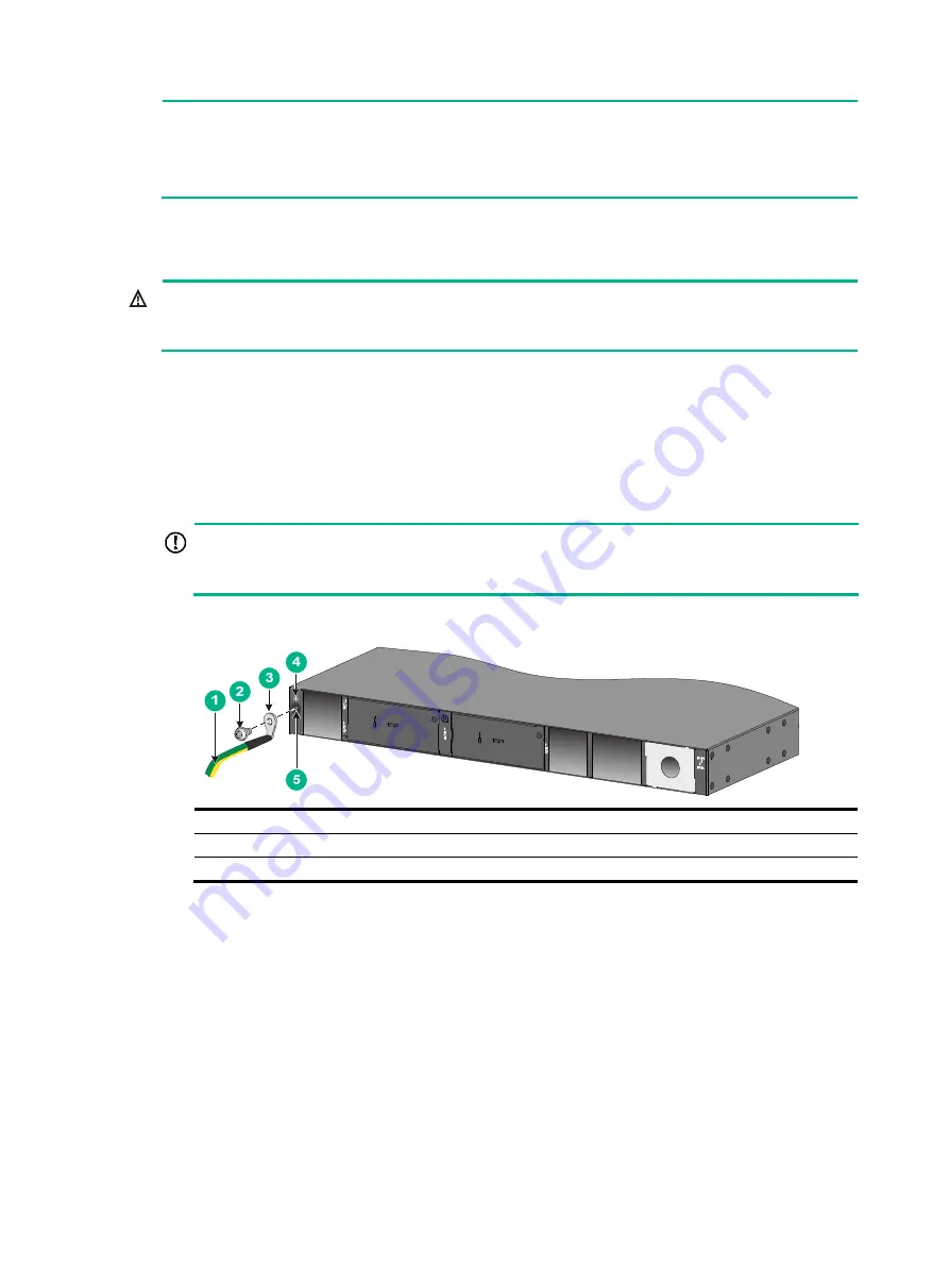
Connecting the grounding cable to the chassis
1.
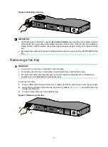
Remove the grounding screw from the rear panel of the chassis.
2.
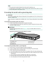
Use the grounding screw to attach the ring terminal of the grounding cable to the grounding
screw hole. Fasten the screw.
IMPORTANT:
Orient the grounding cable as shown in
so you can easily install or remove the
expansion card.
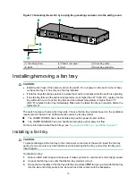
Figure 10 Connecting the grounding cable to the chassis
(1) Grounding cable
(2) Grounding screw
(3) Ring terminal
(4) Grounding sign
(5) Grounding hole
Connecting the grounding cable to a grounding strip
1.
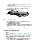
Remove the hex nut of a grounding post on the grounding strip.
2.
Cut the grounding cable to a length required for connecting to the grounding strip.
3.
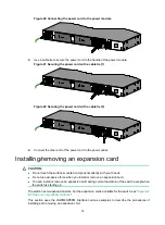
Attach a ring terminal to the grounding cable:
a.
Use a wire stripper to strip 5 mm (0.20 in) of insulation off the end of the grounding cable.
b.
Slide the heat-shrink tubing onto the cable and insert the bare metal part into the end of the
ring terminal.
c.
Use a crimper to secure the metal part of the cable to the ring terminal.
d.
Slide the heat-shrink tubing down the cable until the tube covers the joint.
e.
Use a blow dryer to shrink the tubing around the cable.

