12
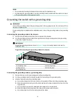
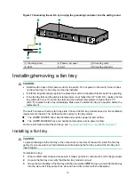
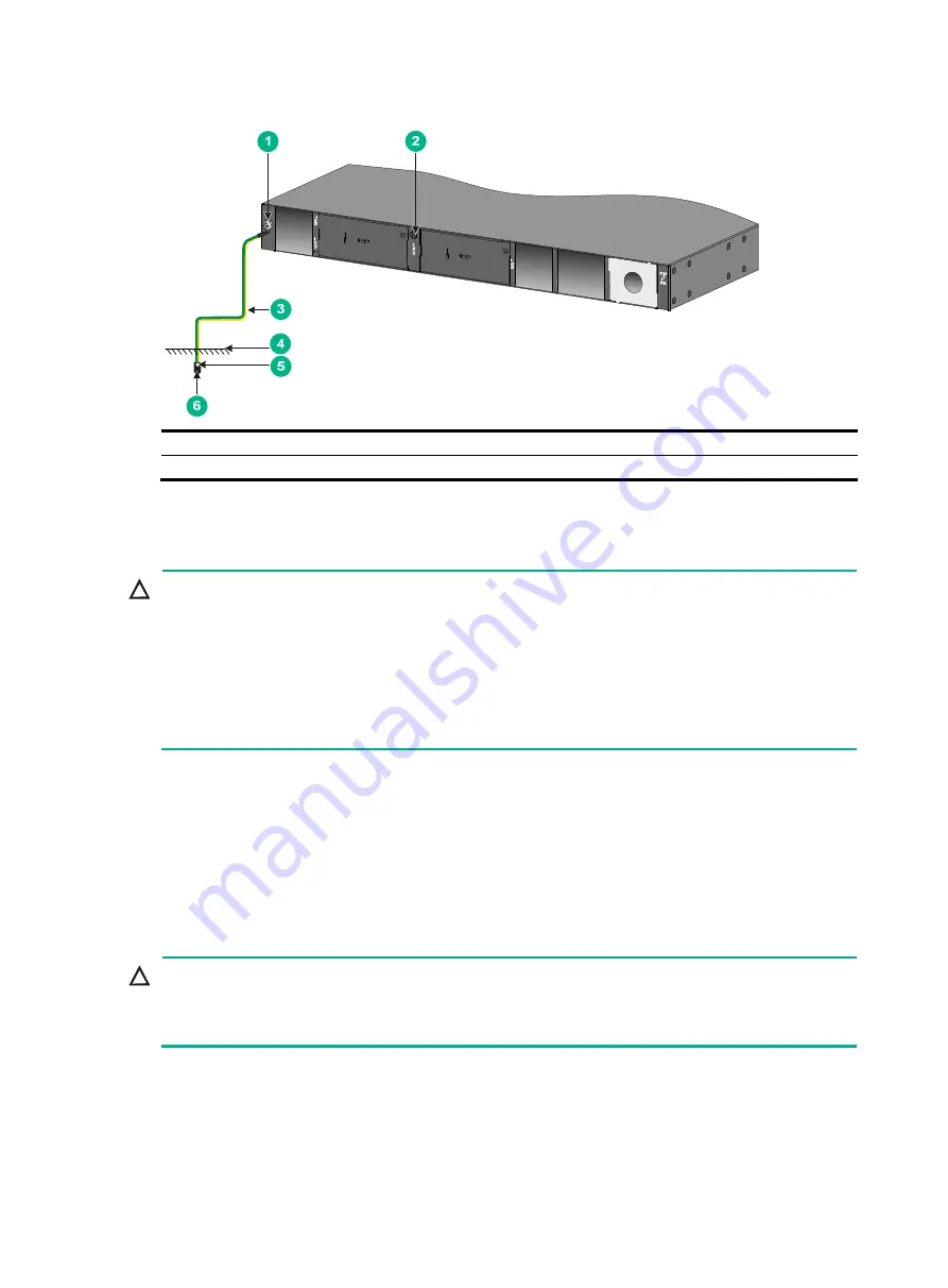
Figure 13 Grounding the switch by burying the grounding conductor into the earth ground
(1) Grounding screw
(2) Chassis rear panel
(3) Grounding cable
(4) Earth
(5) Joint
(6) Grounding conductor
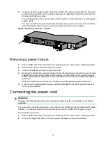
Installing/removing a fan tray
CAUTION:
•
Install two fan trays of the same model on the switch. Do not power on the switch when it does
not have fan trays or has only one fan tray installed.
•
If both fan trays fail during operation, replace them within 2 minutes while the switch is operating.
•
If one fan tray fails and the ambient temperature is not higher than 27°C (80.6°F), replace the fan
tray within 24 hours. If one fan tray fails and the ambient temperature is higher than 27°C
(80.6°F), replace the fan tray immediately. Make sure the failed fan tray is in position before the
replacement.
The switch comes with empty fan tray slots. Choose the fan tray models based on the ventilation
requirement of the site. The air flow direction varies by fan tray model.
•
The LSWM1FANSCE has a blue handle and provides power-to-port air flow.
•
The LSWM1FANSCBE has a red handle and provides port-to-power air flow.
For more information about the fan trays, see "
Appendix B FRUs and compatibility matrixes
."
Installing a fan tray
CAUTION:
To prevent damage to the fan tray or the component connectors of the switch, insert the fan tray
gently. If you encounter any hard resistance while inserting the fan tray, pull out the fan tray and
insert it again.
To install a fan tray:
1.
Wear an ESD wrist strap and make sure it makes good skin contact and is correctly grounded.
2.
Unpack the fan tray and verify that the fan tray model is correct.
3.
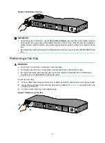
Grasp the two handles of the fan tray with the side marked
TOP
facing up, and slide the fan tray
into the slot until it fully seats in the slot and has a firm contact with the backplane.


