33
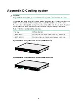
The S6520XE-54QC-HI switch comes with the two fan tray slots empty. You must install two fan trays
of the same model for the switch. In
, two LSWM1FANSCE fan trays are installed in the fan
tray slots. For more information about installing and removing a fan tray, see "
The S6520XE-54QC-HI switch comes with a filler panel in each expansion slot. You can select
expansion cards for the switch as required. In
, two LSWM4SP8PM interface cards are
installed in the expansion slots. For more information about installing and removing an expansion
card, see "
Installing/removing an expansion card
."
Technical specifications
Table 7 Technical specifications
Item S6520XE-54QC-HI
Dimensions (H × W × D)
43.6 × 440 × 360 mm (1.72 × 17.32 × 14.17 in)
Weight
≤
7.5 kg (16.53 lb)
Console port
•
1 × micro USB console port
•
1 × serial console port
You can access the switch only through the micro USB console port if
you connect both ports.
USB port
1
Management Ethernet port
1
SFP+ port
48
QSFP+ port
2
Expansion slot
2, on the rear panel
Power module slot
2, on the rear panel
Fan tray slot
2, on the rear panel
Input voltage
•
AC-input:
{
Rated voltage range: 100 VAC to 240 VAC @ 50 Hz or 60 Hz
{
Max voltage range: 90 VAC to 264 VAC @ 47 Hz to 63 Hz
•
High-voltage
DC-input:
{
Rated voltage range: 240 VDC
{
Max voltage range: 180 VDC to 320 VDC
Static power consumption
•
Single AC input: 62 W
•
Dual AC inputs: 69 W
Maximum power consumption
•
Single AC input: 198 W
•
Dual AC inputs: 201 W
Chassis leakage current
compliance
UL60950-1, EN60950-1, IEC60950-1, GB4943
Melting current of power module
fuse
•
AC-input: 7.56 A/250 V
•
High-voltage DC-input: 7.56 A/240 V
Operating temperature
-
5°C to 45°C (23°F to 113°F)
Relative humidity
5% to 95%, noncondensing
Fire resistance compliance
UL60950-1, EN60950-1, IEC60950-1, GB4943

