background image


43 

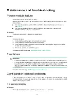
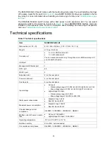
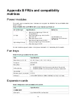
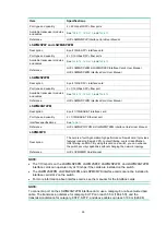
Table 20 System status LED description 

LED mark 

Status 

Description 

SYS 

Steady green 

The switch is operating correctly. 

Flashing green 

The switch is performing power-on self test (POST). 

Steady red 

The switch has failed POST or is faulty. 

Flashing red 

Some ports on the switch have failed POST or are faulty. 

Off 

The switch is powered off or the system fails to start up. 


Power module status LED 

The switch provides two power module slots at the rear panel. For each power module, the switch 
provides a power module status LED on the front panel.  

Table 21 Power module status LED description 

LED mark 

Status 

Description 

PWR1 

Steady green 

A power module is installed in power module slot 1, and the power 
module is outputting power correctly. 

Steady yellow 

A power module is installed in power module slot 1, but no power is 
input to the power module or an output failure has occurred. 

Off 

No power module is installed in power module slot 1. 

PWR2 

Steady green 

A power module is installed in power module slot 2, and the power 
module is outputting power correctly. 

Steady yellow 

A power module is installed in power module slot 2, but the no power 
is input to the power module or an output failure has occurred. 

Off 

No power module is installed in power module slot 2. 


MODE LED 

To show more information about the switch through the SFP+ port status LEDs and QSFP+ port 
status LEDs, the switch provides a MODE LED. The MODE LED indicates the types of information 
that the SFP+ port status LEDs and QSFP+ port status LEDs are showing. 

You can use the port LED mode switching button to change the indication of the MODE LED. 

Table 22 Description for the MODE LED 

LED mark 

Status 

Description 

MODE 

Steady green 

The SFP+ port status LEDs and QSFP+ port status LEDs indicate port rates.

Flashing 
yellow 

The SFP+ port status LEDs and QSFP+ port status LEDs indicate the IRF 
member ID of the switch. For example, if the LEDs for ports 1 to 5 are steady 
green and the other LEDs are off, the IRF member ID of the switch is 5. 


Summary of Contents for S6520XE-54QC-HI

Page 1: ...H3C S6520XE HI Switch Series Installation Guide New H3C Technologies Co Ltd http www h3c com Document version 6W103 20200220 ...

Page 2: ... the property of their respective owners Notice The information in this document is subject to change without notice Every effort has been made in the preparation of this document to ensure accuracy of the contents but all statements information and recommendations in this document do not constitute the warranty of any kind express or implied Environmental protection This product has been designed...

Page 3: ...ose syntax choices keywords or arguments that are optional x y Braces enclose a set of required syntax choices separated by vertical bars from which you select one x y Square brackets enclose a set of optional syntax choices separated by vertical bars from which you select one or none x y Asterisk marked braces enclose a set of required syntax choices separated by vertical bars from which you sele...

Page 4: ... switch such as a Layer 2 or Layer 3 switch or a router that supports Layer 2 forwarding and other Layer 2 features Represents an access controller a unified wired WLAN module or the access controller engine on a unified wired WLAN switch Represents an access point Wireless terminator unit Wireless terminator Represents a mesh access point Represents omnidirectional signals Represents directional ...

Page 5: ...Documentation feedback You can e mail your comments about product documentation to info h3c com We appreciate your comments ...

Page 6: ...Installing removing an expansion card 16 Installing an expansion card 17 Removing an expansion card 18 Verifying the installation 18 Accessing the switch for the first time 19 Setting up the configuration environment 19 Connecting the serial console cable 19 Connecting the micro USB console cable 20 Setting terminal parameters 22 Powering on the switch 22 Setting up an IRF fabric 24 IRF fabric set...

Page 7: ...s 37 Console port 37 Management Ethernet port 37 USB port 37 1 10GBase T autosensing Ethernet port 38 SFP port 38 QSFP port 41 LEDs 42 System status LED 42 Power module status LED 43 MODE LED 43 QSFP port LED 44 SFP port LED 44 Management Ethernet port LEDs 44 Expansion card status LED 45 Port status LED on the expansion card 45 Input status LED and output status LED on the power module 45 Fan tra...

Page 8: ... including expansion cards power modules and fan trays wear an ESD wrist strap to avoid damaging the units Examining the installation site The S6520XE HI switches must be used indoors You can mount your switch in a rack or on a workbench Before installation verify the following items Adequate clearance is reserved at the air inlet and outlet vents for ventilation The rack or workbench has a good v...

Page 9: ... limits on salts acids and sulfides to eliminate corrosion and premature aging of components as shown in Table 2 Table 2 Harmful gas limits in the equipment room Gas Maximum concentration mg m3 SO2 0 2 H2S 0 006 NH3 0 05 Cl2 0 01 EMI All electromagnetic interference EMI sources from outside or inside of the switch and application system adversely affect the switch in the following ways A conductio...

Page 10: ... The laser light emitted from the optical fiber might hurt your eyes The S6520XE HI switch is a Class 1 laser device Installation tools No installation tools are provided with the switch Prepare the following tools yourself Flat blade screwdriver Phillips screwdriver ESD wrist strap ...

Page 11: ...ON Keep the tamper proof seal on a mounting screw on the chassis cover intact and if you want to open the chassis contact H3C for permission Otherwise H3C shall not be liable for any consequence Figure 1 Hardware installation flow ...

Page 12: ...e rear rack posts to the inner surface of the cabinet door is longer than 153 mm 6 02 in orient the bracket arm backward See Rack mounting by using the front and rear mounting brackets Figure 2 Rack mounting procedure by using the front and rear mounting brackets NOTE If a rack shelf is available you can put the switch on the rack shelf slide the switch to an appropriate location and attach the sw...

Page 13: ...re it makes good skin contact and is reliably grounded 2 Attach the front mounting brackets and shoulder screws to the chassis a Align the round holes in the wide flange of one front mounting bracket with the screw holes in the power side mounting position on one side of the chassis b Use M4 screws to attach the mounting bracket to the chassis c Repeat the proceeding two steps to attach the other ...

Page 14: ...esponding cage nuts on the left and right rear rack posts are at the same height b Attach the rear mounting brackets to the rear posts with M6 screws user supplied Do not fully tighten the M6 screws before mounting the switch in the rack Figure 6 Attaching the rear mounting brackets to the rack with the wide flange inside the rack Figure 7 Attaching the rear mounting brackets to the rack with the ...

Page 15: ...he other hand and pushes the chassis into the rack gently Make sure the shoulder screws closely contact with the upper edges of the rear mounting brackets as shown in Figure 8 and Figure 9 c The other person attaches the front mounting brackets with M6 screws user supplied to the front rack posts Make sure the front and rear mounting brackets have securely attached the switch to the rack Figure 8 ...

Page 16: ...e the switch with upside up on the workbench Grounding the switch WARNING Correctly connecting the switch grounding cable is crucial to lightning protection and EMI protection The power input end of the switch has a noise filter whose central ground is directly connected to the chassis to form the chassis ground commonly known as PGND You must securely connect this chassis ground to the earth so t...

Page 17: ...n the screw IMPORTANT Orient the grounding cable as shown in Figure 10 so you can easily install or remove the expansion card Figure 10 Connecting the grounding cable to the chassis 1 Grounding cable 2 Grounding screw 3 Ring terminal 4 Grounding sign 5 Grounding hole Connecting the grounding cable to a grounding strip 1 Remove the hex nut of a grounding post on the grounding strip 2 Cut the ground...

Page 18: ...ding conductor buried in the earth ground If the installation site has no grounding strips but earth ground is available hammer a 0 5 m 1 64 ft or longer angle iron or steel tube into the earth ground to serve as a grounding conductor The dimensions of the angle iron must be a minimum of 50 50 5 mm 1 97 1 97 0 20 in The steel tube must be zinc coated and its wall thickness must be a minimum of 3 5...

Page 19: ...with empty fan tray slots Choose the fan tray models based on the ventilation requirement of the site The air flow direction varies by fan tray model The LSWM1FANSCE has a blue handle and provides power to port air flow The LSWM1FANSCBE has a red handle and provides port to power air flow For more information about the fan trays see Appendix B FRUs and compatibility matrixes Installing a fan tray ...

Page 20: ...NSCE fan tray Removing a fan tray WARNING Do not touch conductors or terminals on the fan trays Do not place the fan tray in moist place Prevent liquid from entering the fan tray Fan trays with faulty internal wiring and conductors require maintenance from maintenance engineers Do not disassemble the faulty fan trays To remove a fan tray 1 Wear an ESD wrist strap and make sure it makes good skin c...

Page 21: ...slot Figure 16 Installation procedure Figure 17 Removal procedure Installing a power module The switch provides two power module slots You can install one power module or two power modules for 1 1 redundancy To install a power module 1 Wear an ESD wrist strap and make sure it makes good skin contact and is reliably grounded 2 Unpack the power module and verify that the power module model is correc...

Page 22: ...wer module with one hand and using the thumb to press the latch towards the handle pull the power module part way out of the slot Then support the power module bottom with the other hand and pull the power module slowly out of the slot along the guide rails Keep the removed power module in an antistatic bag or the package bag for future use 5 If you are not to install a power module install the fi...

Page 23: ... card CAUTION Do not touch the surface mounted components directly with your hands Do not use excessive force when you install or remove an expansion card You can install or remove an expansion card during normal operation of the switch except when the switch is starting up The switch has two expansion slots For the expansion cards available for the switch see Appendix B FRUs and compatibility mat...

Page 24: ...pansion card and perform the following steps a Optional If the expansion card has an ejector lever rotate out the ejector lever as shown by callout 1 in Figure 24 b Gently push the expansion card into the slot along the guide rails until the expansion card has good contact with the chassis as shown by callout 2 in Figure 24 c Optional If the expansion card has an ejector lever rotate in the ejecto...

Page 25: ...ng the guide rails 5 If you are not to install a new expansion card install a filler panel in the slot to prevent dust and ensure good ventilation in the switch Verifying the installation After you complete the installation verify the following information There is enough space for heat dissipation around the switch and the rack or workbench is stable The grounding cable is securely connected The ...

Page 26: ...e yourself or purchase one from H3C Figure 25 Connecting the serial console port to a terminal Connecting the serial console cable A serial console cable is an 8 core shielded cable with a crimped RJ 45 connector at one end for connecting to the serial console port of the switch and a DB 9 female connector at the other end for connecting to the serial port on the console terminal Figure 26 Serial ...

Page 27: ...from a powered off switch first disconnect the switch end Connecting the micro USB console cable 1 Connect the standard USB connector to the USB port of the configuration terminal 2 Connect the micro USB connector to the micro USB console port of the switch 3 Click the following link or copy it to the address bar on a browser to log in to the download page of the USB console driver and download th...

Page 28: ...21 Figure 27 Device Driver Installation Wizard 6 Click Continue Anyway if the following dialog box appears Figure 28 Software Installation 7 Click Finish ...

Page 29: ... user guides for these programs The following are the required terminal settings Bits per second 9 600 Data bits 8 Parity None Stop bits 1 Flow control None Powering on the switch Before powering on the switch verify that the following conditions are met The power cord is correctly connected The input power voltage meets the requirement of the switch The console cable is correctly connected The co...

Page 30: ...ons differ with software versions For more information about Boot ROM menu options see the software matching release notes for the device After the startup completes you can access the CLI to configure the switch For more information about the configuration commands and CLI see H3C S6520XE HI Switch Series Configuration Guides and H3C S6520XE HI Switch Series Command References ...

Page 31: ...ageability IRF fabric setup flowchart Figure 30 IRF fabric setup flowchart To set up an IRF fabric Step Description 1 Plan IRF fabric setup Plan the installation site and IRF fabric setup parameters Planning IRF fabric size and the installation site Identifying the master switch and planning IRF member IDs Planning IRF topology and connections Identifying physical IRF ports on the member switches ...

Page 32: ... equals the total switching capacities of all member switches Plan the installation site depending on your network solution as follows Place all IRF member switches in one rack for centralized high density access Distribute the IRF member switches in different racks to implement the ToR access solution for a data center NOTE For the maximum IRF member devices supported by the S6520XE HI see the re...

Page 33: ...cal port to it When connecting two neighboring IRF member switches you must connect the physical ports of IRF port 1 on one switch to the physical ports of IRF port 2 on the other switch The S6520XE HI switches can provide 10 GE IRF connections through 10GBase T GE SFP ports and 40 GE IRF connections through QSFP ports and you can bind several 10GBase T GE SFP QSFP ports to an IRF port for increas...

Page 34: ...tches If the IRF member switches are far away from one another choose the SFP QSFP transceiver modules with optical fibers If the IRF member switches are all in one equipment room choose twisted pair SFP QSFP QSFP to SFP cables For more information about SFP QSFP QSFP to SFP cables and SFP QSFP transceiver modules see Appendix C Ports and LEDs The following subsections describe several H3C recomme...

Page 35: ...ks side by side to deploy a top of rack ToR solution As a best practice use SFP QSFP transceiver modules and optical fibers to connect the IRF members in a ToR solution Figure 35 shows an example for connecting top of rack IRF member switches 9 switches in this example by using SFP QSFP transceiver modules and optical fibers The topology is the same as Figure 34 Figure 35 ToR cabling ...

Page 36: ...m see H3C Transceiver Modules and Network Cables Installation Guide Verifying the IRF fabric setup To verify the basic functionality of the IRF fabric after you finish configuring basic IRF settings and connecting IRF ports 1 Log in to the IRF fabric through the console port of any member switch 2 Create a Layer 3 interface assign it an IP address and make sure the IRF fabric and the remote networ...

Page 37: ... the issue persists contact H3C Support To replace a power module see Installing removing a power module Fan failure WARNING If both fan trays fail during operation replace them within 2 minutes while the switch is operating If one fan tray fails and the ambient temperature is not higher than 27 C 80 6 F replace the fan tray within 24 hours If one fan tray fails and the ambient temperature is high...

Page 38: ...e does not have any problems and the terminal settings are correct 4 If the issue persists contact H3C Support Garbled terminal display Symptom Terminal display is garbled Solution To resolve the issue 1 Verify that the following settings are configured for the terminal Baud rate 9 600 Data bits 8 Parity none Stop bits 1 Flow control none 2 If the issue persists contact H3C Support ...

Page 39: ...3 Power module slot 2 LED PWR2 14 Power module slot 1 LED PWR1 15 QSFP port LED 16 QSFP port Figure 37 S6520XE 54QC HI rear panel 1 Grounding screw 2 Fan tray 1 3 Expansion card 1 4 Expansion card 2 5 Fan tray 2 6 Power module 1 7 Power module 2 The S6520XE 54QC HI switch comes with power module slot 1 PWR1 empty and power module slot 2 PWR2 installed with a filler panel You can install one or two...

Page 40: ...onsole port 1 micro USB console port 1 serial console port You can access the switch only through the micro USB console port if you connect both ports USB port 1 Management Ethernet port 1 SFP port 48 QSFP port 2 Expansion slot 2 on the rear panel Power module slot 2 on the rear panel Fan tray slot 2 on the rear panel Input voltage AC input Rated voltage range 100 VAC to 240 VAC 50 Hz or 60 Hz Max...

Page 41: ... VDC Max input voltage range 180 to 320 VDC Max output power 250 W You can install one power module or two power modules in 1 1 redundancy for the switch Fan trays Table 9 Fan trays available for the switch Item Specifications Dimensions H W D 40 40 56 mm 1 57 1 57 2 20 in Fan speed 21000 R P M Max airflow 26 CFM Airflow direction LSWM1FANSCE From the power module side to the port side LSWM1FANSCB...

Page 42: ...fications See Table 13 Reference H3C LSWM2XGT2PM LSWM2XGT8PM Interface Cards User Manual LSPM6FWD Description The card is a fourth generation high performance firewall card It provides features including firewall VPN content filtering content identification URL filtering and NAT By using this card on a switch you can enhance the switch security capabilities without changing the network topology Re...

Page 43: ... the distribution frame is preferably not adjacent for example If the device connects to one distribution frame connect port 1 on the device to port 1 on the distribution frame and port 2 on the device to port 3 on the distribution frame If the device connects to two distribution frames connect port 1 on the device to port 1 on distribution frame 1 and port 2 on the device to port 1 on distributio...

Page 44: ...C or management station for loading and debugging software or remote management Table 12 Management Ethernet port specifications Item Specification Connector type RJ 45 Connector quantity 1 Port transmission rate 10 100 1000 Mbps half full duplex Transmission medium and max transmission distance 100 m 328 08 ft over category 5 twisted pair cable Functions and services Switch software and Boot ROM ...

Page 45: ...r SFP ports over a short distance use SFP or SFP cables You can install the GE SFP transceiver modules and cables in Table 14 10 Gbps SFP transceiver modules in Table 15 and 10 Gbps SFP cables in Table 16 in the SFP ports Table 14 GE SFP transceiver modules and cables available for the SFP ports GE SFP transceiver module and cable Central wavelength nm Connector Cable fiber diameter µm Multimode f...

Page 46: ... 9 125 N A 40 km 24 86 miles SFP GE LH80 S M1550 1550 LC Single mode 9 125 N A 80 km 49 71 miles SFP GE LH80 S M1550 D 1550 LC Single mode 9 125 N A 80 km 49 71 miles SFP GE LH100 SM1550 1550 LC Single mode 9 125 N A 100 km 62 14 miles SFP GE LX SM 1310 BIDI TX 1310 RX 1490 LC Single mode 9 125 N A 10 km 6 21 miles SFP GE LX SM 1490 BIDI TX 1490 RX 1310 SFP cable SFP STACK Kit N A 1 5 m 4 92 ft Ta...

Page 47: ... 125 2000 300 m 984 25 ft 500 82 m 269 03 ft 400 66 m 216 54 ft Multi mode 62 5 125 200 33 m 108 27 ft 160 26 m 85 30 ft SFP XG LX SM 1310 1310 LC Single mode 9 125 N A 10 km 6 21 miles SFP XG LX SM 1310 D 1310 LC Single mode 9 125 N A 10 km 6 21 miles SFP XG LX SM 1310 E 1310 LC Single mode 9 125 N A 10 km 6 21 miles Table 16 SFP cables available for the SFP ports Cable description Cable length L...

Page 48: ... 19 in the QSFP ports Table 17 QSFP transceiver modules available for the QSFP ports QSFP transceiver module Central wavelength nm Connector Fiber type and diameter µm Modal bandwidth MHz km Max transmission distance QSFP 40G SR 4 MM850 850 MPO Multi mode 50 125 2000 100 m 328 08 ft 4700 150 m 492 12 ft QSFP 40G CS R4 MM850 850 MPO Multi mode 50 125 2000 300 m 984 25 ft 4700 400 m 1312 33 ft QSFP ...

Page 49: ...nt list of QSFP transceiver modules QSFP cables and QSFP to SFP cables available for the QSFP ports contact H3C Support or marketing staff You can use a QSFP 40G SR4 MM850 or QSFP 40G CSR4 MM850 transceiver module to connect a QSFP port to four SFP ports The QSFP transceiver module and SFP transceiver modules to be connected must be the same in specifications including central wavelength and fiber...

Page 50: ...ule is installed in power module slot 1 PWR2 Steady green A power module is installed in power module slot 2 and the power module is outputting power correctly Steady yellow A power module is installed in power module slot 2 but the no power is input to the power module or an output failure has occurred Off No power module is installed in power module slot 2 MODE LED To show more information about...

Page 51: ...atus LED for each SFP port The SFP port status LED in conjunction with the MODE LED indicates the operating state of the SFP port Table 24 SFP port LED description MODE LED status SFP port LED status Description Steady green rate mode Steady green A transceiver module is installed and a link is present on the port The port is operating at 10 Gbps Flashing green The port is sending or receiving dat...

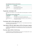
Page 52: ...itch does not support the expansion card or the card has failed Off The expansion slot is empty Port status LED on the expansion card The expansion cards provide a port status LED for each port For more information about the LEDs see the manuals for the expansion cards Input status LED and output status LED on the power module The PSR250 12A and PSR250 12A1 power modules each have a LED on the fro...

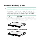
Page 53: ... switch uses hot swappable fan trays You can provide airflow from the port side to the power module side or from power module side to the port side by using different types of fan trays Table 27 Fan trays and their airflow directions Fan tray Airflow direction LSWM1FANSCE From the power module side to the port side and chassis sides LSWM1FANSCBE From the port side and chassis sides to the power mo...

Reviews: