2-11
Installing the switch in a 19-in rack
IMPORTANT:
•
M4 screws are used for attaching the mounting brackets and chassis rails to the chassis. As a
best practice, use a torque of 12 kgf-cm (1.18 Nm) to fasten M4 screws.
•
M6 screws and cage nuts are user supplied. As a best practice, use a torque of 30 kgf-cm (2.94
Nm) to fasten M6 screws.
•
Shoulder screws are used to support the weight of the switch together with rear mounting
brackets. As a best practice, use a torque of 12 kgf-cm (1.18 Nm) to fasten shoulder screws.
Rack-mounting by using front mounting brackets
Attaching the front mounting brackets to the chassis
The switch has one mounting position near the network ports and one mounting position near the
power modules for mounting brackets. You can select one position as needed.
To attach the front mounting brackets to the chassis:
1.
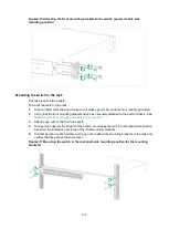
Place the wide flange of the mounting bracket against the chassis side panel. Align the
mounting bracket installation holes with the screw holes in the chassis.
To install the mounting brackets at the port-side mounting position, see
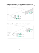
To install the mounting brackets at the power module-side mounting position, see
2.
Fasten the M4 screws to secure the mounting bracket to the switch.
3.
Attach the front mounting bracket to the other side of the chassis in the same way.
Figure2-9 Attaching the front mounting brackets to the switch (port-side mounting position)


