4
•
Use electromagnetic shielding, for example, shielded interface cables, when necessary.
•
To prevent signal ports from getting damaged by overvoltage or overcurrent caused by lightning
strikes, route interface cables only indoors.
Laser safety
WARNING!
•
The switch is a Class 1M laser device.
•
Disconnected optical fibers or transceiver modules might emit invisible laser light. Do not stare
into beams or view directly with optical instruments when the switch is operating.
Installation tools
No installation tools are provided with the switch. Prepare the following tools yourself:
•
ESD wrist strap
•
Flat-blade screwdriver
•
Phillips screwdriver
•
Marker
•
Needle-nose pliers
•
Diagonal pliers
Installation accessories
Before installation, make sure you have all the required installation accessories. If an installation
accessory is damaged or lost, purchase a new one by using the BOM code in
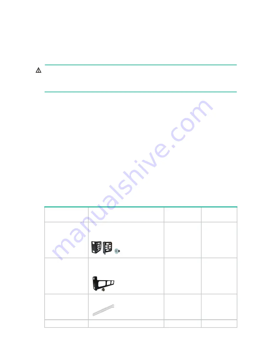
Table1-3 Installation accessories
BOM code
Description
Quantity
Applicable
device models
2150A03X
Front mounting kit, including a pair of
front mounting brackets and eight M4
screws
1 pair, provided
All models
2150A0BP
Rear mounting bracket kit, including a
pair of rear mounting brackets and two
shoulder screws
1 pair, optional
All models
2150A050
1U long slide rail and chassis rail
1 pair, optional
All models
2150A0CP
1U super-short slide rail and chassis rail
1 pair, optional
All models


