4-45
•
Use an SFP+ module and fiber or an SFP+ cable to connect SFP+ ports for a 10-GE IRF
physical connection.
You can bind several ports to an IRF port for increased bandwidth and availability.
Identifying physical IRF ports on the member switches
Identify the physical IRF ports on the member switches according to your topology and connection
scheme.
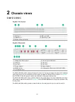
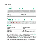
shows the physical ports that can be used for IRF connection and the port use restrictions.
Table4-1 Physical IRF port requirements
Chassis
Candidate physical IRF ports
Requirements
•
S6812-24X6C
•
S6812-48X6C
•
S6813-24X6C
•
S6813-48X6C
All SFP+ ports and QSFP28 ports on the
front panel
•
All physical ports to be bound to an
IRF port must have the same data
rate.
•
The port must operate at its highest
speed.
SFP+ port
—10 Gbps
QSFP28 port
—100 Gbps
Planning the cabling scheme
The cables available for connecting two peer IRF physical ports vary by port type:
•
SFP+ ports
—SFP+ transceiver modules and optical fibers or SFP+ cables. For the available
transceiver modules and cables, see ports in
Hardware Information and Specifications
.
•
QSFP28 ports
—QSFP28 transceiver modules and optical fibers or QSFP28 cables. For the
available transceiver modules and cables, see ports in
Hardware Information and
Specifications
.
For a short-distance IRF connection in an equipment room, use an SFP+ cable or QSFP28 cable.
For a long-distance IRF connection, use SFP+/QSFP28 transceiver modules and optical fibers.
The following subsections describe several H3C recommended IRF connection schemes. All these
schemes use a ring topology.
IMPORTANT:
In these schemes, all physical IRF ports are located on the same side. If physical IRF ports are on
different sides, you must measure the distance between them to select an appropriate cable.
Connecting the IRF member switches in one rack
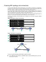
shows an example for connecting four IRF member switches in a rack. The switches in the
) are in the same order as connected in the rack.


