background image

5-2 

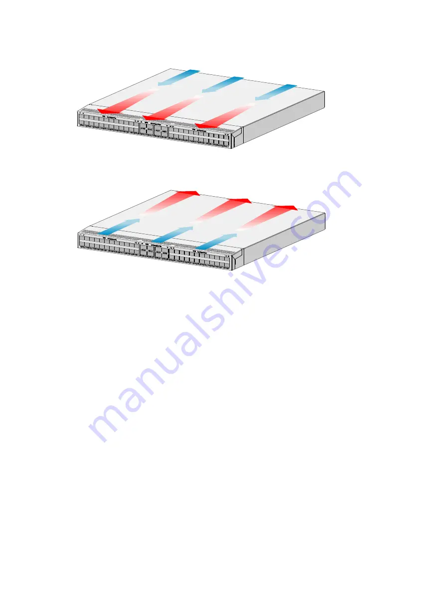
Figure5-3 Airflow from the power supply side to the port side through the S6826-48Y8C 
chassis (with LSWM1FANSA fan trays) 


Figure5-4 Airflow from the port side to the power supply side through the S6826-48Y8C 
chassis (with LSWM1FANSAB fan trays) 


Summary of Contents for S6826 Series

Page 1: ...H3C S6826 S9826 Switch Series Installation Guide New H3C Technologies Co Ltd http www h3c com Document version 5W100 20211129...

Page 2: ...espective owners Notice The information in this document is subject to change without notice All contents in this document including statements information and recommendations are believed to be accur...

Page 3: ...se syntax choices keywords or arguments that are optional x y Braces enclose a set of required syntax choices separated by vertical bars from which you select one x y Square brackets enclose a set of...

Page 4: ...s a Layer 2 or Layer 3 switch or a router that supports Layer 2 forwarding and other Layer 2 features Represents an access controller a unified wired WLAN module or the access controller engine on a u...

Page 5: ...Documentation feedback You can e mail your comments about product documentation to info h3c com We appreciate your comments...

Page 6: ...the rack 2 14 Grounding the switch 2 16 Installing and removing fan trays 2 17 Installing a fan tray 2 17 Removing a fan tray 2 18 Installing and removing power supplies 2 18 Installing a power suppl...

Page 7: ...rotection grounding cable before power on Make sure the operating voltage is in the required range To avoid electrical shocks do not open the chassis while the switch is operating or when the switch i...

Page 8: ...he worst case this might shorten the device s lifetime and even cause communication failure Table1 1 describes the dust concentration limits in the equipment room Table1 1 Dust concentration limit in...

Page 9: ...ncy devices Use electromagnetic shielding for example shielded interface cables when necessary To prevent signal ports from getting damaged by overvoltage or overcurrent caused by lightning strikes ro...

Page 10: ...r permission Otherwise H3C shall not be liable for any consequence caused thereby Figure2 1 Hardware installation flow Start Install the switch Ground the switch Connect power cords Verify the install...

Page 11: ...brackets but also chassis rails and slide rails Rack mounting requirements Figure2 3 S6826 48Y8C chassis dimensions mounting brackets installed at the port side 1 Power supply handle 2 Mounting bracke...

Page 12: ...o 33 62 in A minimum of 800 mm 31 50 in in depth recommended A minimum of 130 mm 5 12 in between the front rack post and the front door A minimum of 550 mm 21 65 in between the front rack post and the...

Page 13: ...ackets Rack mounting rail kit S6826 48Y8 C 1U high one pair See Figure2 7 N A 1U high including one pair of long slide rails and one pair of chassis rails provided See Figure2 9 1U high including one...

Page 14: ...Figure2 9 1U long slide rail and chassis rail 1 Chassis rail 2 Long slide rail Figure2 10 1U short slide rail and chassis rail 1 Chassis rail 2 Short slide rail Figure2 11 1U super short slide rail an...

Page 15: ...Select installation positions for the mounting brackets chassis rails and grounding cable as required Figure2 12 Mounting brackets and grounding cable installation positions on the S6826 48Y8C switch...

Page 16: ...o the network port side 2 Determine the chassis rail installation position If the mounting brackets are installed at the power supply side mounting position install the chassis rails near the port sid...

Page 17: ...eaching out of the chassis Figure2 16 Attaching the mounting brackets and long chassis rails to the S6826 48Y8C switch port side mounting position for the mounting brackets chassis rails reaching out...

Page 18: ...ls not reaching out of the chassis Figure2 19 Attaching the mounting brackets and long chassis rails to the S6826 48Y8C switch power supply side mounting position for the mounting brackets chassis rai...

Page 19: ...the grounding point before you mount the switch in the rack This section uses the primary grounding point on the S9826 32C switch as an example To connect the grounding cable to a grounding point 1 C...

Page 20: ...es two people To mount the switch in the rack 1 Wear an ESD wrist strap and make sure it makes good skin contact and is reliably grounded 2 Verify that the mounting brackets and chassis rails have bee...

Page 21: ...s are the same for the S6826 48Y8C and S9826 32C switches The following figures use the S9826 32C switch as an example Figure2 24 Mounting the S9826 32C switch in the rack power supply side mounting p...

Page 22: ...ground to the earth so the faradism and leakage electricity can be safely released to the earth to minimize EMI susceptibility of the switch To ground the switch 1 As shown in Figure2 26 attach the tw...

Page 23: ...e fan tray and insert it again IMPORTANT Before powering on the switch make sure the fan tray airflow direction and the preferred airflow direction of the switch are the same If they are not the same...

Page 24: ...akes good skin contact and is reliably grounded 2 Grasp the handle of the fan tray with one hand and pull the fan tray part way out of the slot Support the fan tray bottom with the other and pull the...

Page 25: ...LSVM1DC650 installation procedure is the same on the S6826 switch series and S9826 switch series The figures in this section use the S9826 32C switch as an example To install a power supply 1 Wear an...

Page 26: ...supply 1 Wear an ESD wrist strap and make sure it makes good skin contact and is reliably grounded 2 Squeeze the tabs on the power cord connector with your thumb and forefinger and pull the connector...

Page 27: ...er 2 Pull the power cord connector out Figure2 34 Removing the power supply 1 Pivot the latch to the right with your thumb 2 Pull the power supply out Connecting the power cords WARNING Provide a circ...

Page 28: ...ecting a DC power cord 1 Align the power cord plug with the power receptacle on the power supply and insert the plug into the receptacle see Figure2 36 The plug and receptacle are foolproof If you can...

Page 29: ...3 mm 2 or 12 AWG 5 3 mm 2 or 10 AWG Verifying the installation After you complete the installation verify that There is enough space for heat dissipation around the switch and the rack is stable The g...

Page 30: ...example uses a console cable to connect a console terminal PC to the serial console port on the switch Figure3 1 Connecting the serial console port to a terminal Connecting the console cable A serial...

Page 31: ...end to connect to the mini USB console port of the switch and a standard USB Type A connector at the other end to connect to the USB port on the configuration terminal To connect to the configuration...

Page 32: ...3 26 Figure3 3 Device Driver Installation Wizard 6 Click Continue Anyway if the following dialog box appears Figure3 4 Software Installation 7 Click Finish...

Page 33: ...see the user guides for these programs The following are the required terminal settings Bits per second 9600 Data bits 8 Stop bits 1 Parity None Flow control None Powering on the switch 1 Before powe...

Page 34: ...tWare interface and menu options vary by software version For more information about BootWare menu options see the software matching release notes for the device 3 After the startup completes you can...

Page 35: ...r supply has good ventilation 4 If the issue persists contact H3C Support To replace a power supply see Installing and removing power supplies Fan tray failure CAUTION The S6826 48Y8C switch has five...

Page 36: ...e is connected correctly 3 Verify that the console cable does not have any problems and the terminal settings are correct 4 If the issue persists contact H3C Support Garbled display Symptom The config...

Page 37: ...ents available for the switches 3 1 Power supplies 3 1 Fan trays 3 2 4 Ports and LEDs 4 1 Ports 4 1 Console port 4 1 Management Ethernet port 4 1 USB port 4 2 SFP port 4 2 SFP port 4 4 QSFP28 port 4 4...

Page 38: ...port 1 serial console port Management Ethernet port 1 10M 100M 1000M BASE T copper port 1 SFP port 1 10M 100M 1000M BASE T copper port 1 SFP port USB port 1 1 SFP port 2 N A SFP port N A 2 SFP28 port...

Page 39: ...7 C 80 6 F 62 4 dB A 62 9 dB A Chassis leakage current compliance UL60950 1 EN60950 1 IEC60950 1 GB4943 Operating temperature 0 C to 45 C 32 F to 113 F Operating relative humidity 5 to 95 noncondensin...

Page 40: ...16 Copper Management Ethernet port LED ACT 17 System status LED SYS 18 Copper management Ethernet port LED LINK The S6826 48Y8C switch comes with power supply slot PWR1 empty and power supply slot PWR...

Page 41: ...grounding point S9826 32C Figure2 4 Front panel 1 QSFP28 port 2 QSFP28 port LED 3 SFP port 4 SFP port LED Figure2 5 Rear panel 1 Mini USB console port 2 Copper management Ethernet port 3 Serial conso...

Page 42: ...r supplies are installed in the power supply slots The S9826 32C switch comes with the six fan tray slots empty You must install six fan trays of the same model for the switch In Figure2 5 six LSWM1FA...

Page 43: ...switch is fully configured with fan trays of the same model Power supplies WARNING When the switch has power supplies in redundancy you can replace a power supply without powering off the switch Make...

Page 44: ...power supply side to the port side LSWM1FANSAB from the port side to the power supply side Dimensions 40 6 42 5 118 7 mm 1 60 1 67 4 67 in Fan speed 21000 R P M Max airflow 35 CFM Input voltage 12 V...

Page 45: ...rminal Provides connection to the serial port of a local or remote through a pair of modems PC running terminal emulation program Provides connection to an ASCII terminal Provides connection to the US...

Page 46: ...ort supplies power as per USB 2 0 specifications Use only USB 2 0 compliant USB devices for the USB port The port might not identity USB devices that are not compliant with USB 2 0 NOTE USB devices fr...

Page 47: ...t LSWM2STK 1 2 m 3 94 ft LSWM3STK 3 m 9 84 ft LSTM1STK 5 m 16 40 ft Table4 6 10 GE SFP fiber cables available for the SFP ports 10 GE SFP fiber cable Max transmission distance SFP XG D AOC 7M 7 m 22 9...

Page 48: ...ANT If you install an SFP GE T or SFP GE T D transceiver module in an SFP port the port can operate only at 1 Gbps SFP port The S6826 48Y8C switch provides two SFP ports You can install FE SFP transce...

Page 49: ...56 1300 05 1304 58 1309 14 LC Single mode 9 125 N A 10 km 6 21 miles QSFP 100G LR4L WDM1 300 Four lanes 1264 5 to 1277 5 1284 5 to 1297 5 1304 5 to 1317 5 1324 5 to 1337 5 LC Single mode 9 125 N A 2...

Page 50: ...tral wavelength nm Connector Fiber type and diameter m Modal bandwidth MHz km Max transmission distance QSFP 40G SR 4 MM850 850 MPO PC polished 12 core Multi mode 50 125 2000 100 m 328 08 ft 4700 150...

Page 51: ...sion distance LSWM1QSTK3 1 m 3 28 ft LSWM1QSTK4 3 m 9 84 ft LSWM1QSTK5 5 m 16 40 ft NOTE You can use a QSFP 40G SR4 MM850 or QSFP 40G CSR4 MM850 transceiver module to connect a QSFP port to four SFP p...

Page 52: ...ation Guide Table4 17 25G SFP28 copper cables available for the SFP28 ports 25G SFP28 copper cable Max transmission distance SFP 25G D CAB 1M 1 m 3 28 ft SFP 25G D CAB 3M 3 m 9 84 ft Table4 18 25G SFP...

Page 53: ...s operating at 100 Gbps Flashing green The port is sending or receiving data at 100 Gbps Steady yellow A transceiver module or cable has been correctly installed The port has a link and is operating a...

Page 54: ...and is operating at 1 Gbps Flashing green The port is sending or receiving data at 1 Gbps Steady yellow A transceiver module or cable has been correctly installed The port has a link and is operating...

Page 55: ...w The port is operating at 100 Mbps Flashing yellow The port is receiving or sending data at 100 Mbps Fan tray alarm LEDs The LSWM1FANSA and LSWM1FANSAB fan trays each provide an alarm LED Table4 26 D...

Page 56: ...ou plan the installation site for the switch Table5 1 Cooling system for the switch Switch model Available fan trays Airflow direction S9826 32C S6826 48Y8 C LSWM1FANSA From the power supply side to t...

Page 57: ...from the power supply side to the port side through the S6826 48Y8C chassis with LSWM1FANSA fan trays Figure5 4 Airflow from the port side to the power supply side through the S6826 48Y8C chassis with...

Reviews: