29
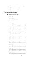
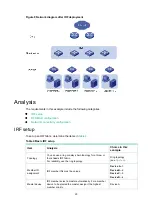
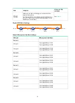
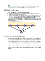
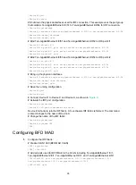
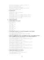
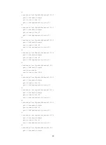
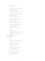
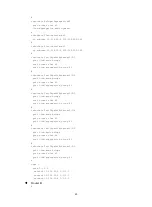
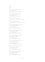
# Create VLAN-interface 1000, and configure a MAD IP address for each member device on
the interface.
[IRF] interface vlan-interface 1000
[IRF-Vlan-interface1000] mad bfd enable
[IRF-Vlan-interface1000] mad ip address 192.168.2.1 24 member 1
[IRF-Vlan-interface1000] mad ip address 192.168.2.2 24 member 2
[IRF-Vlan-interface1000] mad ip address 192.168.2.3 24 member 3
[IRF-Vlan-interface1000] mad ip address 192.168.2.4 24 member 4
[IRF-Vlan-interface1000] quit
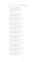
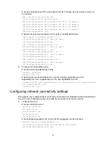
# Disable the spanning tree feature on the ports in the BFD MAD VLAN.
[IRF] interface ten-gigabitethernet 1/0/1
[IRF-Ten-GigabitEthernet1/0/1] undo stp enable
[IRF-Ten-GigabitEthernet1/0/1] quit
[IRF] interface ten-gigabitethernet 2/0/1
[IRF-Ten-GigabitEthernet2/0/1] undo stp enable
[IRF-Ten-GigabitEthernet2/0/1] quit
[IRF] interface ten-gigabitethernet 3/0/1
[IRF-Ten-GigabitEthernet3/0/1] undo stp enable
[IRF-Ten-GigabitEthernet3/0/1] quit
[IRF] interface ten-gigabitethernet 4/0/1
[IRF-Ten-GigabitEthernet4/0/1] undo stp enable
[IRF-Ten-GigabitEthernet4/0/1] quit
2.
Configure the intermediate device:
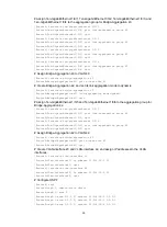
# Create VLAN 1000 (BFD MAD VLAN).
<Sysname> system-view
[Sysname] vlan 1000
# Add all ports used for BFD MAD to the VLAN, including GigabitEthernet 1/0/1,
GigabitEthernet 1/0/2, GigabitEthernet 1/0/3, and GigabitEthernet 1/0/4.
[Sysname-vlan1000] port gigabitethernet 1/0/1 gigabitethernet 1/0/2 gigabitethernet
1/0/3 gigabitethernet 1/0/4
[Sysname-vlan3] quit
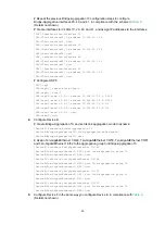
Configuring network connectivity settings
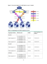
This example only contains network connectivity configuration for Department B and Department C.
The core router configuration does not include the connection to the public network.
1.
Configure Router A:
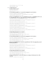
# Create VLANs 40 and 42.
<RouterA> system-view
[RouterA] vlan 40
[RouterA-vlan40] quit
[RouterA] vlan 42
[RouterA-vlan42] quit
# Create Bridge-Aggregation 40, and set its link aggregation mode to dynamic.
[RouterA] interface bridge-aggregation 40
[RouterA-Bridge-Aggregation40] link-aggregation mode dynamic
[RouterA-Bridge-Aggregation40] quit


