9
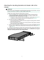
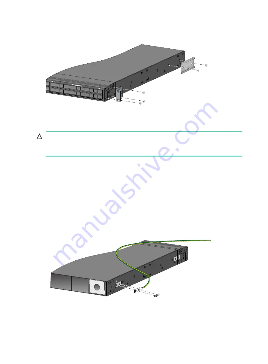
Figure 10 Attaching the mounting brackets and chassis rails to an S6890-54HF switch
(network port-side mounting position for the mounting brackets)
Connecting the grounding cable to the chassis
CAUTION:
The primary grounding point and auxiliary grounding point 1 are located on the left panel of the
chassis. If you use one of these grounding points, you must connect the grounding cable to the
grounding point before you mount the switch in the rack.
The grounding cable and grounding screw that come with the switch are applicable to both the
primary and auxiliary grounding points.
To connect the grounding cable:
1.
Choose a grounding point as required.
This example uses the primary grounding point.
2.
Unpack the grounding cable and grounding screws.
3.
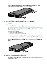
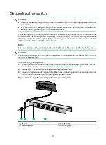
Use two grounding screws to attach the two-hole grounding lug of the grounding cable to the
grounding holes at the grounding point. Use a screwdriver to tighten the screws. See
As a best practice, use a torque of 20 kgf-cm (1.96 Nm) to fasten the grounding screws.
Figure 11 Attaching the grounding cable to the primary grounding point on an S6890-54HF
switch
Attaching the slide rails to the rack
The installation procedure is similar for short and long slide rails. The following procedure uses long
slide rails as an example.

