background image

33 

Item S6890-54HF S6890-30HF S6890-44HF 

Minimum power 
consumption 


Single AC input: 140 W


Single DC input: 135 W


Dual AC inputs: 155 W


Dual DC inputs: 148 W


Single AC input: 117 W 


Single DC input: 112 W 


Dual AC inputs: 122 W 


Dual DC inputs: 117 W 

 Single 

AC 

input: 

148 W 


Single DC input: 
151 W 

 Dual 

AC 

inputs: 

159 W 


Dual DC inputs: 
159 W 

Maximum power 
consumption 


Single AC input: 327 W


Single DC input: 320 W


Dual AC inputs: 340 W


Dual DC inputs: 330 W


Single AC input: 258 W 


Single DC input: 249 W 


Dual AC inputs: 260 W 


Dual DC inputs: 247 W 

 Single 

AC 

input: 

244 W 


Single DC input: 
250 W 

 Dual 

AC 

inputs: 

249 W 


Dual DC inputs: 
255 W 

Chassis leakage 
current compliance

 UL 

60950-1 

 EN 

60950-1 

 IEC 

60950-1 

 GB4943 

 UL 

60950-1 

 EN 

60950-1 

 IEC 

60950-1 

 GB4943 

 UL 

60950-1 

 EN 

60950-1 

 IEC 

60950-1 

 GB4943 

Operating 
temperature 

0°C to 45°C (32°F to 113°F)

0°C to 45°C (32°F to 113°F) 

0°C to 45°C (32°F to 
113°F) 

Operating humidity

5% RH to 95% RH, 
noncondensing 

5% RH to 95% RH, 
noncondensing 

5% RH to 95% RH, 
noncondensing 

Fire resistance 
compliance 

 UL 

60950-1 

 EN 

60950-1 

 IEC 

60950-1 

 GB4943 

 UL 

60950-1 

 EN 

60950-1 

 IEC 

60950-1 

 GB4943 

 UL 

60950-1 

 EN 

60950-1 

 IEC 

60950-1 

 GB4943 


Chassis ordering information 

To purchase an S6890 chassis, contact the sales agent or H3C sales personnel. 

Table 9 S6890 chassis ordering information 

Product code 

Product name 

Description 

0235A2AB 

S6890-54HF 

H3C S6890-54HF L3 Ethernet switch 

0235A3L5 

S6890-30HF 

H3C S6890-30HF L3 Ethernet switch 

0235A2H8 

S6890-44HF 

H3C S6890-44HF L3 Ethernet switch 


Summary of Contents for S6890 Series

Page 1: ...H3C S6890 Switch Series Installation Guide New H3C Technologies Co Ltd http www h3c com Document version 6W104 20200415 ...

Page 2: ...r respective owners Notice The information in this document is subject to change without notice All contents in this document including statements information and recommendations are believed to be accurate but they are presented without warranty of any kind express or implied H3C shall not be liable for technical or editorial errors or omissions contained herein Environmental protection This prod...

Page 3: ...tax choices keywords or arguments that are optional x y Braces enclose a set of required syntax choices separated by vertical bars from which you select one x y Square brackets enclose a set of optional syntax choices separated by vertical bars from which you select one or none x y Asterisk marked braces enclose a set of required syntax choices separated by vertical bars from which you select a mi...

Page 4: ...as a Layer 2 or Layer 3 switch or a router that supports Layer 2 forwarding and other Layer 2 features Represents an access controller a unified wired WLAN module or the access controller engine on a unified wired WLAN switch Represents an access point Represents a wireless terminator unit Represents a wireless terminator Represents a mesh access point Represents omnidirectional signals Represents...

Page 5: ...Documentation feedback You can e mail your comments about product documentation to info h3c com We appreciate your comments ...

Page 6: ...4 Installing and removing power supplies 14 Installing a power supply 15 Removing a power supply 16 Connecting the power cords 18 Connecting the power cord for an LSVM1AC650 LSVM1AC300 PSR450 12A or PSR450 12A1 power supply 19 Connecting the power cord for a PSR450 12AHD power supply 19 Connecting the power cord for an LSVM1DC650 or LSVM1DC300 power supply 20 Connecting the power cord for a PSR450...

Page 7: ...Power supplies 34 Fan trays 36 Appendix C Ports and LEDs 37 Ports 37 Console port 37 Management Ethernet port 37 USB port 38 SFP port 39 QSFP28 port 41 Clock port 43 LEDs 43 System status LED 43 QSFP28 port LED 44 SFP port LED 44 Management Ethernet port LED 44 Fan tray alarm LED 45 Appendix D Cooling system 46 ...

Page 8: ... chassis while the switch is operating or when the switch is just powered off When replacing field replaceable units FRUs including power supplies and fan trays wear an ESD wrist strap to avoid damaging the units Examining the installation site The switch must be used indoors Make sure the installation site meets the following requirements Adequate clearance is reserved at the air inlet and outlet...

Page 9: ...ver three days NOTE Dust diameter 5 μm The equipment room must also meet limits on salts acids and sulfides to eliminate corrosion and premature aging of components as shown in Table 2 Table 2 Harmful gas limits in the equipment room Gas Maximum concentration mg m3 SO2 0 2 H2S 0 006 NH3 0 05 Cl2 0 01 EMI All electromagnetic interference EMI sources from outside or inside of the switch and applicat...

Page 10: ...able 3 Installation accessories Product code Description Quantity Applicable device models 2150A03X Mounting bracket 1 pair All S6890 models 2114A09C Power supply filler panel 1 All S6890 models 2150A050 Slide rail and chassis rail 1 pair All S6890 models 0404A0UU Grounding cable 1 All S6890 models 04042967 Console cable 1 All S6890 models Installation tools No installation tools are provided with...

Page 11: ...r proof seal on a mounting screw on the chassis cover intact and if you want to open the chassis contact H3C for permission Otherwise H3C shall not be liable for any consequence caused thereby Installation flowchart Figure 1 Installation flowchart ...

Page 12: ...ne pair See Figure 2 1U high one pair of long slide rails and one pair of chassis rails provided See Figure 4 1U high one pair of short slide rails and one pair of chassis rails optional See Figure 3 Figure 2 Mounting brackets provided with the switch Figure 3 1U short slide rail and chassis rail 1 Chassis rail 2 Short slide rail Figure 4 1U long slide rail and chassis rail 1 Chassis rail 2 Long s...

Page 13: ...hassis width of an S6890 44F switch mounting brackets installed at the port side 1 Power supply handle 2 Mounting bracket Follow these guidelines when you install the switch in a 19 inch rack The distance between the front and rear posts of the rack must meet the requirements described in Table 5 As a best practice make sure the rack has a minimum depth of 800 mm 31 50 in so that the rack door can...

Page 14: ... rack posts and the rear door Port side 130 mm 5 12 in 540 mm 21 26 in Power supply side 80 mm 3 15 in 590 mm 23 23 in Mounting brackets and grounding cable installation positions The switch provides two mounting bracket installation positions on the side panels one near the power supply side and one near the port side as shown in Figure 8 The switch has a primary grounding point with a grounding ...

Page 15: ... the mounting brackets at the port side mounting position see Figure 10 2 Determine the chassis rail installation position If the mounting brackets are installed at the power supply side mounting position install the chassis rails near the port side If the mounting brackets are installed at the network port side mounting position install the chassis rails near the power supply side 3 Place the cha...

Page 16: ...he primary and auxiliary grounding points To connect the grounding cable 1 Choose a grounding point as required This example uses the primary grounding point 2 Unpack the grounding cable and grounding screws 3 Use two grounding screws to attach the two hole grounding lug of the grounding cable to the grounding holes at the grounding point Use a screwdriver to tighten the screws See Figure 11 As a ...

Page 17: ...eople To mount the switch in the rack 1 Wear an ESD wrist strap and make sure it makes good skin contact and is reliably grounded 2 Verify that the mounting brackets and chassis rails have been securely attached to the switch chassis 3 Verify that the slide rails have been correctly attached to the rear rack posts 4 Attach cage nuts user supplied to the front rack posts and make sure they are at t...

Page 18: ...13 Mounting an S6890 54HF switch in the rack Power supply side mounting position for the mounting brackets Figure 14 Mounting an S6890 54HF switch in the rack Port side mounting position for the mounting brackets ...

Page 19: ...ibility of the switch NOTE The power and grounding terminals positions in the figures in this section are for illustration only CAUTION Connect the grounding cable to the grounding system in the equipment room Do not connect it to a fire main or lightning rod To connect the grounding cable 1 Attach the two hole grounding lug of the grounding cable to a grounding point on the chassis For more infor...

Page 20: ... you encounter a hard resistance while inserting the fan tray pull out the fan tray and insert it again Multiple fan trays are available for the switch Select fan trays for the switch as needed For the available fan trays and their specifications see Fan trays The installation procedure is the same for the fan trays The following procedure installs an LSWM1FANSA fan tray in an S6890 54HF switch To...

Page 21: ...port the fan tray bottom with the other and pull the fan tray completely out of the slot 3 Put the removed fan tray in an antistatic bag Figure 17 Removing an LSWM1FANSA fan tray from an S6890 54HF switch Installing and removing power supplies WARNING To avoid bodily injury and device damage strictly follow the procedures in Figure 18 and Figure 19 to install and remove a power supply Provide a se...

Page 22: ... switch 3 Unpack the power supply and verify that the power supply model is correct 4 Correctly orient the power supply with the words on the power supply upward Grasping the handle of the power supply with one hand and supporting its bottom with the other and insert the power supply slowly into the slot along the guide rails Follow the forward inertia of the power supply when inserting it into th...

Page 23: ...and forefinger and pull the connector out as shown in Figure 22 To remove the power cord from a PSR450 12D power supply use a flat head screwdriver to remove the screws on the power cord connector and then pull the connector out as shown in Figure 23 To remove the power cord from a PSR450 12AHD power supply release the jaw of the cable clamp open the cable clamp and then pull the connector out as ...

Page 24: ...ower supply 1 Press the tabs on the power cord connector with your thumb and forefinger 2 Pull the power cord connector out Figure 23 Removing the power cord from a PSR450 12D power supply 1 Remove the screws on the power cord connector 2 Pull the power cord connector out ...

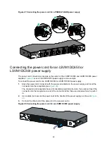
Page 25: ...Pull the power cord connector out Figure 25 Removing the power supply from an S6890 54HF switch 1 Pivot the latch to the right with your thumb 2 Pull the power supply out Connecting the power cords WARNING Provide a circuit breaker for each power input When you connect a power cord make sure the circuit breaker is switched off 1 2 3 ...

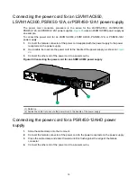
Page 26: ... supply 2 Use a cable tie to secure the power cord to the handle of the power supply as shown in Figure 26 3 Connect the other end of the power cord to a power source Figure 26 Connecting the power cord for an LSVM1AC650 power supply 1 Cable tie 2 Fasten the cable tie to secure the power cord to the handle of the power supply Connecting the power cord for a PSR450 12AHD power supply 1 Slide the ca...

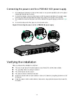
Page 27: ... 1 Align the power cord connector with the power receptacle on the power supply and insert the connector into the receptacle see Figure 28 The connector and receptacle have a disorientation rejection structure If you cannot insert the connector into the receptacle re orient the connector rather than use excessive force to push it in 2 Use a cable tie to secure the power cord to the handle of the p...

Page 28: ...ly as shown in Figure 29 4 Connect the other end of the power cord to a power source Figure 29 Connecting the power cord for a PSR450 12D power supply Verifying the installation After you complete the installation verify that There is enough space for heat dissipation around the switch and the rack is stable The grounding cable is securely connected The correct power source is used The power cords...

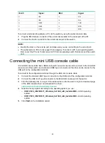
Page 29: ...to connect a console terminal PC to the serial console port on the switch Figure 30 Connecting the serial console port to a terminal Connecting the console cable A serial console cable is an 8 core cable with a crimped RJ 45 connector at one end for connecting to the serial console port of the switch and a DB 9 female connector at the other end for connecting to the serial port on the console term...

Page 30: ...mini Type B connector at one end to connect to the mini USB console port of the switch and a standard USB Type A connector at the other end to connect to the USB port on the configuration terminal To connect to the configuration terminal through the USB mini console cable 1 Connect the standard USB Type A connector to the USB port of the configuration terminal 2 Connect the USB mini Type B connect...

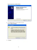
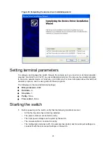
Page 31: ...24 Figure 32 Device Driver Installation Wizard 6 Click Continue Anyway if the following dialog box appears Figure 33 Software Installation 7 Click Finish ...

Page 32: ...ms see the user guides for these programs The following are the required terminal settings Bits per second 9600 Data bits 8 Stop bits 1 Parity None Flow control None Starting the switch 1 Before powering on the switch verify that the following conditions are met All the fan tray slots have a fan tray installed The power cords are connected correctly The input power voltage is as required by the sw...

Page 33: ...nu options vary by software version For more information about BootWare menu options see the software matching release notes for the device 3 After the startup completes you can access the CLI to configure the switch For more information about the configuration commands and CLI see H3C S6890 Switch Series Configuration Guides and H3C S6890 Switch Series Command References ...

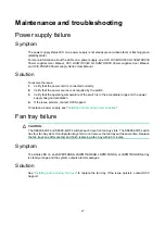
Page 34: ...mperature of the switch is in the acceptable range and the power supply has good ventilation 4 If the issue persists contact H3C Support To replace a power supply see Installing and removing power supplies Fan tray failure CAUTION The S6890 54HF and S6890 44HF switches each have five fan tray slots The S6890 30HF switch has four fan tray slots If multiple fan trays fail do not remove the fan trays...

Page 35: ...e is connected correctly 3 Verify that the console cable does not have any problems and the terminal settings are correct 4 If the issue persists contact H3C Support Garbled display Symptom The configuration terminal has a garbled display Solution To resolve the issue 1 Verify that the following settings are configured for the terminal Baud rate 9 600 Data bits 8 Parity None Stop bits 1 Flow contr...

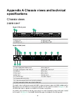
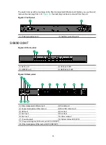
Page 36: ...2 Power supply 2 13 System status LED SYS 14 Copper management Ethernet port LED LINK ACT 15 Fiber management Ethernet port LED LINK ACT The switch comes with power supply slot PWR1 empty and power supply slot PWR2 installed with a filler panel You can install one or two power supplies for the switch as needed In Figure 36 two LSVM1AC650 power supplies are installed in the power supply slots The s...

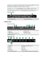
Page 37: ...unding point S6890 30HF Figure 38 Front panel 1 SFP port 2 SFP port LED 3 QSFP28 port 4 QSFP28 port LED Figure 39 Rear panel 1 Fiber management Ethernet port 2 Console port 3 Copper management Ethernet port 4 Mini USB console port 5 USB port 6 Fan tray 1 7 Fan tray 2 8 Fan tray 3 9 Fan tray 4 10 Power supply 1 11 Power supply 2 12 System status LED SYS 13 Copper management Ethernet port LED LINK A...

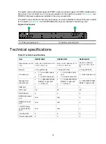
Page 38: ...ug in the fiber management Ethernet port Before you use the port remove the dust plug from it In Figure 39 the dust plug has been removed from the port Figure 40 Left panel 1 Primary grounding point 2 Auxiliary grounding point S6890 44HF Figure 41 Front panel 1 SFP port 2 SFP port LED 3 QSFP28 port 4 QSFP28 port LED 5 1PPS ToD time synchronization port 6 SMB clock output port 7 SMB clock input por...

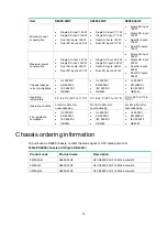
Page 39: ...ifications Table 8 Technical specifications Item S6890 54HF S6890 30HF S6890 44HF Dimensions H W D 43 6 440 460 mm 1 72 17 32 18 11 in 43 6 440 460 mm 1 72 17 32 18 11 in 44 440 460 mm 1 73 17 32 18 11 in Weight 13 kg 28 66 lb 10 kg 22 05 lb 10 kg 22 05 lb Console port 1 mini USB console port 1 serial console port 1 mini USB console port 1 serial console port 1 serial console port Management Ether...

Page 40: ...compliance UL 60950 1 EN 60950 1 IEC 60950 1 GB4943 UL 60950 1 EN 60950 1 IEC 60950 1 GB4943 UL 60950 1 EN 60950 1 IEC 60950 1 GB4943 Operating temperature 0 C to 45 C 32 F to 113 F 0 C to 45 C 32 F to 113 F 0 C to 45 C 32 F to 113 F Operating humidity 5 RH to 95 RH noncondensing 5 RH to 95 RH noncondensing 5 RH to 95 RH noncondensing Fire resistance compliance UL 60950 1 EN 60950 1 IEC 60950 1 GB...

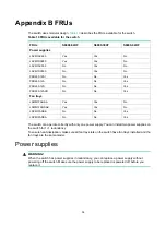
Page 41: ...Fan trays LSWM1FANSA Yes Yes No LSWM1FANSAB Yes Yes No LSPM1FANSB No No Yes LSPM1FANSA No No Yes The switch can operate correctly with only one power supply You can install two power supplies on the switch for 1 1 redundancy To ensure heat dissipation make sure all fan tray slots on the switch have fan trays installed and the fan trays are the same model Power supplies WARNING When the switch has ...

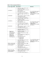
Page 42: ...power 315 W Fuse melting current 25 A 250 V PSR450 12A airflow from the power supply side to the port side PSR450 12A1 airflow from the port side to the power supply side Rated input voltage 100 VAC to 240 VAC 50 Hz or 60 Hz Max AC input voltage 90 VAC to 290 VAC 47 Hz to 63 Hz Rated high voltage DC input voltage 240 VDC Max high voltage DC input voltage 180 VDC to 320 VDC Max output power 450 W F...

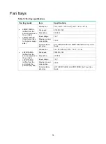
Page 43: ... Max airflow 35 CFM Input voltage 12 V Maximum power consumption 30 W Documentation reference H3C LSWM1FANSA LSWM1FANSAB Fan Trays User Guide LSPM1FANSA airflow from the power supply side to the port side LSPM1FANSB airflow from the port side to the power supply side Dimensions 40 40 28 mm 1 57 1 57 1 10 in Fan speed 20000 R P M Max airflow 20 CFM Input voltage 12 V Maximum power consumption 9 8 W...

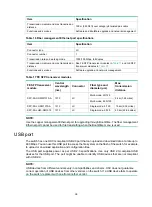
Page 44: ...ing a terminal emulation program Table 14 Mini USB console port specifications Item Specification Connector type USB mini Type B Compliant standard USB 2 0 Transmission baud rate 9600 bps default to 115200 bps Services Provides connection to an ASCII terminal Provides connection to the USB port of a local PC running a terminal emulation program Management Ethernet port The switch has two managemen...

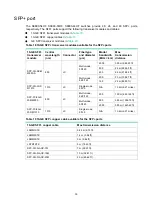
Page 45: ... SM1310 A 1310 LC Single mode 9 125 15 km 9 32 miles SFP FE LH40 SM1310 1310 LC Single mode 9 125 40 km 24 86 miles NOTE Use the copper management Ethernet port for upgrading through BootWare The fiber management Ethernet port cannot be used for file transmitting when the BootWare menu is used USB port The switch has one OHCI compliant USB 2 0 port that can upload and download data at a rate up to...

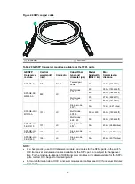
Page 46: ...M M850 A 850 LC Multi mode 50 125 2000 300 m 984 25 ft 500 82 m 269 03 ft 400 66 m 216 54 ft Multi mode 62 5 125 200 33 m 108 27 ft 160 26 m 85 30 ft SFP XG LX S M1310 1310 LC Single mode 9 125 N A 10 km 6 21 miles SFP FC 8G S W MM850 850 LC Multi mode 62 5 125 200 150 m 492 126 ft Multi mode 50 125 500 380 m 1246 72 ft 2000 500 m 1640 42 ft SFP FC 8G L W SM1310 1310 LC Single mode 9 125 N A 10 km...

Page 47: ...1 miles Multi mode 50 125 500 or 400 550 m 1804 46 ft Multi mode 62 5 125 500 550 m 1804 46 ft SFP GE LH4 0 SM1310 1310 LC Single mode 9 125 N A 40 km 24 86 miles SFP GE LH4 0 SM1550 1550 LC Single mode 9 125 N A 40 km 24 86 miles SFP GE LH8 0 SM1550 1550 LC Single mode 9 125 N A 80 km 49 71 miles NOTE As a best practice use H3C transceiver modules and cables for the SFP ports on the switch H3C tr...

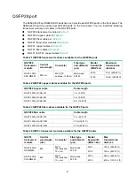
Page 48: ...00G SR4 MM850 850 nm MPO PC polished 12 fiber Multi mode 50 125 2000 70 m 229 66 ft 4700 100 m 328 08 ft Table 22 QSFP28 copper cables available for the QSFP28 ports QSFP28 copper cable Cable length QSFP 100G D CAB 1M 1 m 3 28 ft QSFP 100G D CAB 3M 3 m 9 84 ft QSFP 100G D CAB 5M 5 m 16 40 ft Table 23 QSFP28 fiber cables available for the QSFP28 ports QSFP28 fiber cable Cable length QSFP 100G D AOC...

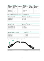
Page 49: ...istance LSWM1QSTK0 1 m 3 28 ft LSWM1QSTK1 3 m 9 84 ft LSWM1QSTK2 5 m 16 40 ft Table 26 QSFP fiber cables available for the QSFP28 ports QSFP fiber cable Max transmission distance QSFP 40G D AOC 7M 7 m 22 97 ft QSFP 40G D AOC 10M 10 m 32 81 ft QSFP 40G D AOC 20M 20 m 65 62 ft Table 27 QSFP to SFP copper cables available for the QSFP28 ports QSFP28 to SFP28 copper cable Cable length LSWM1QSTK3 1 m 3...

Page 50: ...ts signals at 2 048 Mbps Used for time synchronization between devices and between the device and terminals Table 29 1PPS ToD time synchronization port specifications Item Specification Connector type RJ 45 Port standard QB B 016 2010 Service You can configure the port as a time synchronization input or output port Used for time synchronization between devices and between the device and GPS receiv...

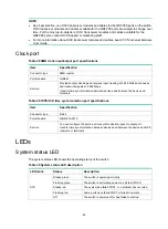
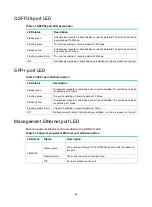
Page 51: ...ady green A transceiver module or cable has been correctly installed The port has a link and is operating at 10 Gbps Flashing green The port is sending or receiving data at 10 Gbps Steady yellow A transceiver module or cable has been correctly installed The port has a link and is operating at 1 Gbps Flashing yellow 3 Hz The port is sending or receiving data at 1 Gbps Off No transceiver module or c...

Page 52: ... green The port is receiving or sending data at 1000 Mbps Steady yellow The port is operating at 100 Mbps Flashing yellow The port is receiving or sending data at 100 Mbps Fan tray alarm LED Each fan tray has an alarm LED Table 35 Description for the alarm LED on the fan trays Status Description On The fan tray is faulty Off The fan tray is operating correctly or no power is being input ...

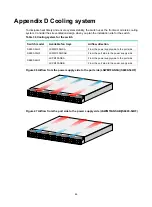
Page 53: ...tch model Available fan trays Airflow direction S6890 54HF S6890 30HF LSWM1FANSA From the power supply side to the port side LSWM1FANSAB From the port side to the power supply side S6890 44HF LSPM1FANSA From the power supply side to the port side LSPM1FANSB From the port side to the power supply side Figure 46 Airflow from the power supply side to the port side LSWM1FANSA S6890 54HF Figure 47 Airf...

Reviews: