43
NOTE:
•
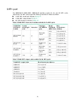
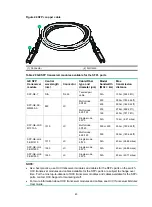
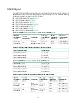
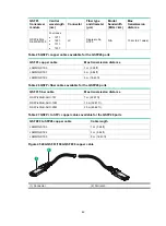
As a best practice, use H3C transceiver modules and cables for the QSFP28 ports on the switch.
H3C transceiver modules and cables available for the QSFP28 ports are subject to change over
time. For the most up-to-date list of H3C transceiver modules and cables available for the
QSFP28 ports, contact H3C Support or marketing staff.
•
For more information about H3C transceiver modules and cables, see
H3C Transceiver Modules
User Guide
.
Clock port
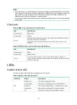
Table 28 SMB clock input/output port specifications
Item Specification
Connector type
SMB coaxial
Port standard
GJB681
Service
Provides output clocking and receives input clocking at 2.048 MHz and receives
and transmits signals at 2.048 Mbps.
Used for time synchronization between devices and between the device and
terminals.
Table 29 1PPS/ToD time synchronization port specifications
Item Specification
Connector type
RJ-45
Port standard
QB-B-016-2010
Service
You can configure the port as a time synchronization input or output port.
Used for time synchronization between devices and between the device and GPS
receivers or terminals.
LEDs
System status LED
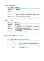
The system status LED shows the operating status of the switch.
Table 30 System status LED description
LED mark
Status
Description
SYS
Steady green
The switch is operating correctly.
Flashing green
The switch is performing power-on self test (POST).
Steady red
The system has failed POST, or a problem has occurred.
Flashing red
Some ports have failed POST or failed to operate.
Off
The switch is powered off or has failed to start up.

