20
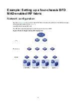
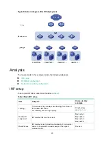
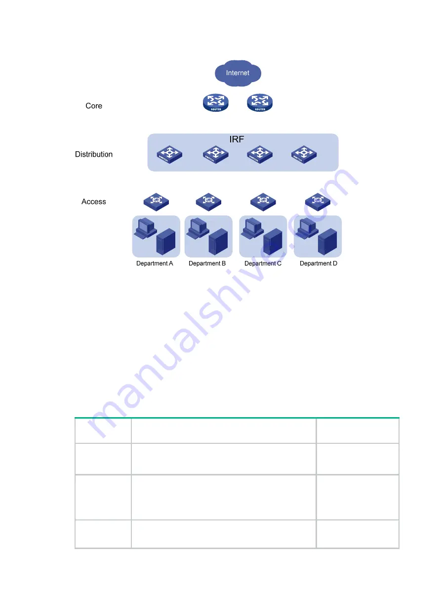
Figure 8 Network diagram after IRF deployment
Analysis
The requirements in this example include the following categories:
•
•
•
Network connectivity configuration
IRF setup
To set up an IRF fabric, determine the items in
.
Table 4 Basic IRF setup
Item Analysis
Choice in this
example
Topology
You can use a ring or daisy-chain topology for a three- or
four-chassis IRF fabric.
For reliability, use the ring topology.
Ring topology
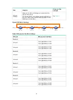
(see
).
Member ID
assignment
IRF member IDs must be unique.
Device A
—1.
Device B
—2.
Device C
—3.
Device D
—4.
Master device
IRF members elect a master automatically. For a member
device to be elected the master, assign it the highest
member priority.
Device A.


