background image

Operation Manual – MSTP 
H3C S9500 Series Routing Switches 

Chapter 1  MSTP Configuration


1-5 


  Note: 

Rules for configuration BPDU comparison:  

z


The configuration BPDU that has the lowest root bridge ID has the highest priority.  

z


For configuration BPDUs with the same root bridge ID, they will be compared by 
their root path costs. If the root path cost in a configuration BPDU plus the path cost 
corresponding to this port is S, the configuration BPDU with the smallest S value 
has the highest priority.  

z


For configuration BPDUs with the same root bridge ID and the same root path cost, 
they will be compared by their designated bridge IDs, then their designated port IDs, 
and then the IDs of the ports through which they are received. The smaller the ID, 
the higher the message priority.  


z


Selection of the root bridge  

At network initialization, each STP-compliant device on the network assumes itself to 
be the root bridge, with the root bridge ID being its own device ID. By exchanging 
configuration BPDUs, the devices compare one another’s root bridge ID. The device 
with the smallest root bridge ID is elected as the root bridge.  

z


Selection of the root port and designated ports  

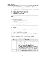
The process of selecting the root port and designated ports is as follows:  

Table 1-3 

Selection of the root port and designated ports  

Step


Description 


The root port is the port through which the optimum configuration BPDU 
was received. 


Based on the configuration BPDU and the path cost of the root port, the 
device generates a designated port configuration BPDU for each of the 
rest ports as follows: 

z


Using the root bridge ID of the configuration BPDU of the root port as 
the root bridge ID.  

z


Using the sum of the root path cost of the configuration BPDU of the 
root port and the path cost corresponding to the root port as the root 
path cost.  

z


Using the local device ID as the designated bridge ID.  

z


Using the local port ID as the designated port ID. 


Summary of Contents for S9500 Series

Page 1: ...H3C S9500 Series Routing Switches Operation Manual Hangzhou H3C Technologies Co Ltd http www h3c com Manual Version T2 081655 20080530 C 2 03 Product Version S9500 CMW520 R2132...

Page 2: ...InnoVision and HUASAN are trademarks of Hangzhou H3C Technologies Co Ltd All other trademarks that may be mentioned in this manual are the property of their respective owners Notice The information i...

Page 3: ...commands Organization H3C Configuration Manual is organized as follows Part Contents 00 Product Overview includes Obtaining the Documentation Product Features and Features 01 Access Volume includes Et...

Page 4: ...nfiguration MPLS L3VPN Configuration MPLS Hybrid Insertion Configuration and GRE Configuration 06 QoS ACL Volume includes QoS Configuration and ACL Configuration 07 Security Volume includes 802 1x Con...

Page 5: ...y Alternative items are grouped in braces and separated by vertical bars A minimum of one or a maximum of all can be selected x y Optional alternative items are grouped in square brackets and separate...

Page 6: ...cription Warning Means reader be extremely careful Improper operation may cause bodily injury Caution Means reader be careful Improper operation may cause data loss or damage to equipment Note Means a...

Page 7: ...describes z POS port overview z POS port configuration GVRP GVRP is a GARP application The volume describes z GARP overview z GVRP configuration Link Aggregation Link aggregation means aggregating se...

Page 8: ...configuration z VLAN types z Super VLAN overview and configuration z Isolate user VLAN overview and configuration QinQ QinQ is a technique that enables packets to be transmitted across the operators b...

Page 9: ...e 1 4 1 1 5 Configuring Physical State Change Suppression on an Ethernet Interface 1 5 1 1 6 Configuring Loopback Testing on an Ethernet Interface 1 5 1 1 7 Configuring a Manual Port Group 1 6 1 1 8 C...

Page 10: ...Configuring Physical State Change Suppression on an Ethernet Interface Optional Configuring Loopback Testing on an Ethernet Interface Optional Configuring a Manual Port Group Optional Configuring Traf...

Page 11: ...d to provide internetworking support between different countries regions or devices of different manufacturers The regenerator section trace byte J0 is usually set to a section access point identifier...

Page 12: ...ly z Half duplex mode half Interfaces operating in this mode can either send or receive packets at a given time z Auto negotiation mode auto Interfaces operating in this mode determine their duplex mo...

Page 13: ...Mbps or auto negotiation z When an O E converter is used for an interface set the duplex mode of the interface to auto for the interface to operate normally 1 1 4 Configuring Flow Control on an Ethern...

Page 14: ...cal link state changes link delay delay time Required Defaults to 1 second 1 1 6 Configuring Loopback Testing on an Ethernet Interface You can enable loopback testing to check whether the Ethernet int...

Page 15: ...iginal configurations will be restored 1 1 7 Configuring a Manual Port Group To make the configuration task easier for users certain devices allow users to configure on a single port as well as on mul...

Page 16: ...Ethernet interface view interface interface type interface number Enter Ethernet interface view or port group view Enter port group view port group manual port group name aggregation agg id Use eithe...

Page 17: ...Statistics Complete the following configuration tasks to configure the time interval for collecting interface statistics Use the display interface command to display the interface statistics within th...

Page 18: ...size is set in the range 9193 to 10240 10240 takes effect 1 1 11 Configuring the MDI Mode of an Ethernet Interface You can connect an Ethernet interface with a crossover or straight through cable dep...

Page 19: ...ce MAC address is that of the VLAN interface which the outbound interface corresponds to However It is required in some cases that the source MAC addresses of packets forwarded through different inter...

Page 20: ...er Available in any view Display the brief information of Ethernet interfaces display brief interface interface type interface number begin include exclude text Available in any view Display the ports...

Page 21: ...ggable optical modules display transceiver interface interface type interface number Available in any view Display the radio frequency identification RFID information of pluggable optical modules disp...

Page 22: ...onfiguration 1 1 1 1 Overview 1 1 1 1 1 SONET SDH 1 1 1 1 2 POS 1 1 1 2 Configuring a POS Interface 1 1 1 3 Displaying and Maintaining POS Interfaces 1 3 1 4 POS Interface Configuration Example 1 3 1...

Page 23: ...reducing signal loss and investment in devices 1 1 2 POS Packet over SONET SDH POS is a technology popular in WAN and MAN POS maps length variable packets directly to SONET synchronous payloads and u...

Page 24: ...exadecimal 16 for C2 In SDH framing the defaults are 15 0x0 for both J0 and J1 In SONET framing the defaults are 0x01 for J0 and 62 0x0 for J1 Set the framing format frame format sdh sonet Optional Th...

Page 25: ...ng on POS interfaces z If a physical interface is idle or has no cable connection shut down it with the shutdown command to avoid interface anomalies that may result from interference z As the shutdow...

Page 26: ...k protocol ppp SwitchA Pos1 1 1 mtu 1500 SwitchA Pos1 1 1 shutdown SwitchA Pos1 1 1 undo shutdown 2 Configure Switch B Configure interface POS 4 1 1 SwitchB system view System View return to User View...

Page 27: ...If your switch is connected to another switch directly check that the clock mode of the local POS interface is opposite to that on the connected POS interface Symptom 2 The physical layer is up but t...

Page 28: ...1 1 1 GARP 1 1 1 1 2 GVRP 1 4 1 1 3 Protocols and Standards 1 4 1 2 Configuring GVRP 1 5 1 2 1 Configuring GVRP Functions 1 5 1 2 2 Configuring GARP Timers 1 5 1 3 Displaying and Maintaining GVRP 1 7...

Page 29: ...registration protocol GARP provides a mechanism that allows GARP participants in a LAN to distribute propagate and register with other participants some attributes such as VLAN IDs or multicast addres...

Page 30: ...oin timer to set the interval between the two sending operations z Leave timer Starts upon receipt of a Leave message If no Join message has been received from the requesting entity before this timer...

Page 31: ...GARP PDUs GARP PDU structure Message structure Attribute List structure Attribute structure Protocol ID Message N End Mark Attribute 1 End Mark Attribute Type Attribute Length Attribute Event Attribut...

Page 32: ...on The VLAN registration information propagated by GVRP includes both manually configured local static entries and dynamic entries from other devices GVRP provides the following three registration mod...

Page 33: ...commands Depending on the view you accessed the subsequent configuration takes effect on a port or all ports in a port group Enable GVRP on the port gvrp Required Disabled by default Configure the GV...

Page 34: ...mer or Leave timer garp timer hold join leave timer value Optional The default is 10 centiseconds for the Hold timer 20 centiseconds for the Join timer and 60 centiseconds for the Leave timer When con...

Page 35: ...the GARP statistics reset garp statistics interface interface list Available in user view 1 4 GVRP Configuration Example 1 4 1 GVRP Configuration Example I I Network requirements Configure GVRP for dy...

Page 36: ...port SysnameB Ethernet1 1 2 gvrp SysnameB Ethernet1 1 2 quit Create VLAN 3 a static VLAN SysnameB vlan 3 SysnameB vlan3 return 3 Verify the configuration Display dynamic VLAN information on Switch A S...

Page 37: ...ll Enable GVRP on Ethernet 1 1 1 SysnameA Ethernet1 1 1 gvrp Set the GVRP registration mode to fixed on the port SysnameA Ethernet1 1 1 gvrp registration fixed SysnameA Ethernet1 1 1 quit Create VLAN...

Page 38: ...he switches Set the forbidden GVRP registration mode on the trunk port of Switch A and keep the default normal mode on the trunk port of Switch B II Network diagram Figure 1 4 Network diagram for GVRP...

Page 39: ...s SysnameB interface ethernet 1 1 2 SysnameB Ethernet1 1 2 port link type trunk SysnameB Ethernet1 1 2 port trunk permit vlan all Enable GVRP on Ethernet 1 1 2 SysnameB Ethernet1 1 2 gvrp SysnameB Eth...

Page 40: ...on 1 5 1 3 Load Sharing in a Link Aggregation Group 1 6 1 4 Service Loop Group 1 7 1 5 Link Aggregation Port Group 1 7 Chapter 2 Link Aggregation Configuration 2 1 2 1 Configuring Link Aggregation 2 1...

Page 41: ...up each other This section covers these topics z LACP z Consistency Considerations for Ports in an Aggregation Note Note the following when employing link aggregation on an S9500 routing switch z Up...

Page 42: ...configurations In a manual or static LACP aggregation the selected ports share the same operational key 1 1 2 Consistency Considerations for Ports in an Aggregation Group To participate in load sharin...

Page 43: ...proaches to Link Aggregation Two ways are available for implementing link aggregation as described in Manual Link Aggregation and Static LACP link aggregation 1 2 1 Manual Link Aggregation I Overview...

Page 44: ...You need to avoid the situation however as the selected unselected state of a port may become different after a reboot Note Currently the number of the selected ports in a manual aggregation group cr...

Page 45: ...ort or those located on a board different from the master port because of hardware restriction Member ports in up state can be selected if they have the configuration same as that of the master port T...

Page 46: ...to ensure consistency As one configuration change may involve multiple ports this can become troublesome if you need to do that port by port As a solution you may add the ports into an aggregation por...

Page 47: ...ort belongs to VLAN 1 For ports that are already in a service loop group you can perform configurations that do not conflict with the service loop group for them such as QoS Note Currently for the S95...

Page 48: ...tion Manual Link Aggregation H3C S9500 Series Routing Switches Chapter 1 Link Aggregation Overview 1 8 For more information about port groups refer to Ethernet Interface Configuration in the Access Vo...

Page 49: ...g a Manual Link Aggregation Group Follow these steps to configure a manual aggregation group To do Use the command Remarks Enter system view system view Create a manual aggregation group link aggregat...

Page 50: ...Enter Ethernet interface view interface interface type interface number Configure the port LACP priority lacp port priority port priority value Optional 32768 by default Assign the Ethernet port to t...

Page 51: ...oup To do Use the command Remarks Enter system view system view Configure a name for a link aggregation group link aggregation group agg id description agg name Required Not configured by default Caut...

Page 52: ...enced by a module or the service loop group contains ports whose attributes conflict with the intended service type z You can use the undo link aggregation group command to remove a service loop group...

Page 53: ...type agg id Available in any view Display summaries for all link aggregation groups display link aggregation summary Available in any view Display detailed information about specified or all link aggr...

Page 54: ...net 1 1 1 SwitchA Ethernet1 1 1 port link aggregation group 1 SwitchA Ethernet1 1 1 quit SwitchA interface ethernet 1 1 2 SwitchA Ethernet1 1 2 port link aggregation group 1 SwitchA Ethernet1 1 2 quit...

Page 55: ...g 1 2 1 2 Configuring Local Port Mirroring 1 4 1 3 Configuring Remote Port Mirroring 1 5 1 3 1 Configuring a Remote Source Mirroring Group on the Source Device 1 5 1 3 2 Configuring a Remote Destinati...

Page 56: ...s 1 1 Introduction to Port Mirroring Port mirroring is to copy the packets passing through a port called a mirroring port to another port called the monitor port connected with a monitoring device for...

Page 57: ...cal remote source and remote destination The following subsections describe how local port mirroring and remote port mirroring are implemented I Local port mirroring In local port mirroring all packet...

Page 58: ...ort in the remote probe VLAN z Intermediate device Intermediate devices if any are devices located in between the source device and the destination device An intermediate device forwards mirrored pack...

Page 59: ...rts 1 2 Configuring Local Port Mirroring Configuring local port mirroring is to configure local mirroring groups A local mirroring group comprises one or multiple mirroring ports and one monitor port...

Page 60: ...orts in it 1 3 Configuring Remote Port Mirroring Configuring remote port mirroring is to configure remote mirroring groups When doing that configure the remote source mirroring group on the source dev...

Page 61: ...ing ports In Ethernet interface view quit Required Use either approach In system view you can assign a list of ports to the mirroring group at a time In interface view you can assign only the current...

Page 62: ...LAN operating as a remote probe VLAN you need to remove the VLAN from the remote mirroring group first with the undo mirroring group remote probe vlan command Removing the probe VLAN can invalidate th...

Page 63: ...robe vlan id If the port is a trunk port port trunk permit vlan rprobe vlan id Assign the monitor port to the remote probe VLAN If the port is a hybrid port port hybrid vlan rprobe vlan id tagged unta...

Page 64: ...ted to port Ethernet 1 1 1 of Switch C through Switch A z Host B is connected to port Ethernet 1 1 2 of Switch C through Switch B z A data monitoring server is connected to port Ethernet 1 1 3 of Swit...

Page 65: ...Configuration Example I Network requirements On a network shown in Figure 1 5 z Host A is connected to port Ethernet 1 1 1 of Switch A z Host B is connected to port Ethernet 1 1 2 of Switch A z Port...

Page 66: ...t mirroring group Sysname mirroring group 1 remote source Create VLAN 2 Sysname vlan 2 Sysname vlan2 quit Configure VLAN 2 as the remote probe VLAN of the remote port mirroring group Add port Ethernet...

Page 67: ...iew Configure port Ethernet 1 1 1 as a trunk port and configure the port to permit the packets of VLAN 2 Sysname interface ethernet 1 1 1 Sysname Ethernet1 1 1 port link type trunk Sysname Ethernet1 1...

Page 68: ...5 Configuring Ringlet Selection Table 1 11 1 5 1 Adding a static ringlet selection entry 1 12 1 5 2 Configuring default ringlet selection 1 12 1 6 Configuring Rate Limiting 1 12 1 7 Configuring Statio...

Page 69: ...layer protocol designed for transferring mass data services over MANs It can operate on synchronous optical network synchronous digital hierarchy SONET SDH dense wavelength division multiplexing DWDM...

Page 70: ...o adjacent stations are connected by a pair of unidirectional logical channels called links transmitting in opposite directions These two links form a span A span on which data frames are not allowed...

Page 71: ...when it reaches the destination station or when its time to live TTL expires Different from traditional ring technologies where unicast frames are removed from the ring at the source station RPR adopt...

Page 72: ...performs automatic topology discovery to collect such information as the number of stations ring state order of the stations on the ring to build a topology database This database does not change afte...

Page 73: ...re used When a station on the ring starts initializing or detects a topology change it sends TP frames to propagate topology information throughout the network When doing that it sends the first nine...

Page 74: ...the point of failure to the opposing ringlet The two ringlets thus form a closed single ring around the point of the failure As shown in Figure 1 6 after the span between station A and station B fail...

Page 75: ...llowing protection hierarchy listed in the order of decreasing severity z Forced switch FS z Signal fail SF related to current physical status z Signal degrade SD related to current physical status z...

Page 76: ...ransits to the idle protection state after entering the automatic protection state z Hold off timer defines the delay for the physical layer PHY to report a protection request after detecting a link f...

Page 77: ...nd For how to configure them refer to Ethernet Port Configuration z RPR logical ports support STP QoS and ACL 1 1 8 Protocols and Standards The RPR implementation follows the following document IEEE80...

Page 78: ...default Caution All the stations on an RPR ring must adopt the same protection mode for the ring to operate normally 1 4 Configuring Protection Reversion Mode Two protection reversion modes are availa...

Page 79: ...nistratively configured to specify the ringlet for delivering a frame to a destination station z Dynamic ringlet selection table is built dynamically based on the topology database z Default ringlet s...

Page 80: ...Static ringlet selection entries take effect only when the RPR ring is closed 1 5 2 Configuring default ringlet selection Follow these steps to configure default ringlet selection To do Use the comman...

Page 81: ...he lowest priority Follow these steps to assign reserved bandwidths to service classes To do Use the command Remarks Enter system view system view Enter RPR logical interface view interface interface...

Page 82: ...nterface view interface interface type interface number Configure the weight of the station rpr weight ringlet0 ringlet1 value Optional The value argument is an exponent of 2 By default the fairness w...

Page 83: ...low these steps to configure an RPR POS interface To do Use the command Remarks Enter system view system view Enter RPR POS interface view interface rprpos interface number Required Configure SD 1 and...

Page 84: ...ill be lost as a result z The rpr port type command can only take effect on 10 Gbps POS and 10GE physical ports It cannot take effect on 2 5 Gbps POS ports 1 11 Configuring Station Name Follow these s...

Page 85: ...on an RPR logical interface For each tunnel you need to specify its frame copying station In addition to distinguish traffic destined to the same MAC address but using different tunnels you need to co...

Page 86: ...Test the connectivity to a specific station rpr echo mac mac address c value r ringlet0 ringlet1 reverse s ringlet0 ringlet1 t value Required If the number of test frames is not specified c value 5 te...

Page 87: ...ce type interface number Display RPR VLAN tunnels display rpr tunnel vlan vlan id1 to vlan id2 all valid invalid interface type interface number Note The above table shows the display command with the...

Page 88: ...steps to configure Station B through Station E Configure a static ringlet selection entry for frames destined for Station B to travel Ringlet 1 Sysname Ten GigabitEthernet1 1 1 rpr static rs 000f e25...

Page 89: ...0 0 000f e257 0004 1 2 dynamic 0 0 0 0 000f e257 0005 1 1 dynamic 0 0 0 0 Total entries 4 1 16 2 RPR VLAN Tunnel Configuration Examples I Network requirements On an RPR network station A uses interfa...

Page 90: ...t vlan 10 Configure a tunnel for VLAN 10 traffic to reach station D Sysname Ten GigabitEthernet1 1 1 rpr tunnel vlan 10 dest mac 000f e200 8582 ringlet1 Verify the configuration of the RPR VLAN tunnel...

Page 91: ...Overview 1 1 1 1 1 Types of OAMPDUs 1 1 1 1 2 OAM Connection Establishment 1 2 1 1 3 OAM Standards 1 5 1 2 OAM Configuration Task List 1 5 1 3 Configuring Basic OAM Functions 1 5 1 4 Configuring Link...

Page 92: ...ntly Ethernet OAM is mainly used to address common link related issues on the last mile By enabling Ethernet OAM on two devices connected by a point to point connection you can monitor the status of t...

Page 93: ...AMPDUs and Loopback control OAMPDUs are commonly used which are described as follows z Information OAMPDUs are used for passing the state information about an Ethernet OAM entity including the informa...

Page 94: ...cesses Those operating in passive OAM mode however wait and respond to OAM connection establishment requests and take corresponding operations The following table compares active OAM mode with passive...

Page 95: ...nterval exceeds the threshold Error frame period event An error frame period event occurs if the number of frame errors in specific number of received frames exceeds the threshold Error frame seconds...

Page 96: ...ests and the peer responds to them If the peer operates in the loopback mode it returns all the PDUs to the senders along the original paths Performing remote loopback testing periodically helps to de...

Page 97: ...sent by their peers z No OAM connection can be established between two OAM entities operating in passive OAM mode z With OAM enabled you cannot change the OAM operating mode To do so you need to disab...

Page 98: ...be greater than the corresponding detection interval otherwise no error frame second event can be created To save bandwidth you can configure OAM to report an error event when the number of errors det...

Page 99: ...ling OAM loopback testing results in all the data communications being stopped After OAM loopback testing is disabled all the ports involved will be shut down and then brought up z OAM loopback testin...

Page 100: ...statistics about the error frames received by Switch A II Network diagram Figure 1 2 Network diagram for OAM configuration III Configuration procedure 1 Configure Switch A Configure Ethernet 4 1 2 to...

Page 101: ...d 1 2 Configure Switch B Configure Ethernet 4 1 2 to operate in active OAM mode the default OAM mode and enable OAM for it Sysname system view Sysname interface ethernet 4 1 2 Sysname Ethernet4 1 2 oa...

Page 102: ...uring Ports as Edge Ports 1 29 1 3 11 Configuring Whether Ports Connect to Point to Point Links 1 30 1 3 12 Configuring the Mode a Port Uses to Recognize Send MSTP Packets 1 31 1 3 13 Enabling the MST...

Page 103: ...1 45 1 8 2 Configuration Procedure 1 45 1 8 3 Configuration Examples 1 45 1 9 Configuring Protection Functions 1 46 1 9 1 Configuration Prerequisites 1 48 1 9 2 Enabling the BPDU Guard Function 1 48 1...

Page 104: ...s in the network by exchanging information with one another and eliminate loops by selectively blocking certain ports until the loop structure is pruned into a loop free network structure This avoids...

Page 105: ...an STP network a root port is a port on a non root bridge device Among the ports on an STP enabled device the root port has the lowest path cost to the root bridge The root port takes charge of commu...

Page 106: ...ed bridge for the LAN is Switch B and the designated port is BP2 on Switch B Note All the ports on the root bridge are designated ports 4 Path cost Path cost is a reference value used for link selecti...

Page 107: ...e root path cost is 0 designated bridge ID is the device ID and the designated port is the local port z Selection of the optimum configuration BPDU Each device sends out its configuration BPDU and rec...

Page 108: ...the network assumes itself to be the root bridge with the root bridge ID being its own device ID By exchanging configuration BPDUs the devices compare one another s root bridge ID The device with the...

Page 109: ...iguration BPDU As a result the port can receive BPDUs but cannot send BPDUs or forward data Note When the network topology is stable only the root port and designated ports forward traffic while other...

Page 110: ...ration BPDU from Switch B that is 1 0 1 BP1 As the configuration BPDU of the local port that is 0 0 0 AP1 is superior to the received configuration BPDU the received configuration BPDU is discarded z...

Page 111: ...ration BPDU Switch B discards the received configuration BPDU BP1 0 0 0 AP1 BP2 1 0 1 BP2 Switch B z Switch B compares the configuration BPDUs of all its ports and determines that the configuration BP...

Page 112: ...uperior CP2 acts as a designated port and Switch C sends the generated configuration BPDU through CP2 periodically Root port CP1 0 0 0 AP2 Designated port CP2 0 10 2 CP2 z Next port CP2 receives the u...

Page 113: ...ved the configuration BPDU and the received configuration BPDU is superior to the configuration BPDU of the port the device will increase message age carried in the configuration BPDU by a certain rul...

Page 114: ...newly elected root port or designated port must wait twice the forward delay time before it begins to forward data The delay ensures that the new configuration BPDU has been propagated throughout the...

Page 115: ...ts of all VLANs are forwarded along the same spanning tree 2 Features of MSTP The multiple spanning tree protocol MSTP overcomes the shortcomings of STP and RSTP In addition to support for rapid netwo...

Page 116: ...d z They have the same region name z They have the same VLAN to MSTI mapping configuration z They have the same MSTP revision level configuration z They are physically linked with one another In area...

Page 117: ...ons in a switched network If you regard each MST region as a device the CST is a spanning tree computed by these devices through STP or RSTP The red lines in Figure 1 4 describe the CST 5 CIST Jointly...

Page 118: ...ng switch is connected to a third party s device that supports boundary port recognition the third party s device may malfunction in recognizing a boundary port 10 Roles of ports MSTP calculation invo...

Page 119: ...learns MAC addresses and forwards user traffic z Learning the port learns MAC addresses but does not forwards user traffic z Discarding the port neither learns MAC addresses nor forwards user traffic...

Page 120: ...h MST region through computing and at the same time MSTP regards each MST region as a single device and generates a CST among these MST regions through computing The CST and ISTs constitute the CIST o...

Page 121: ...ridge while all others as leaf nodes Task Remarks Configuring an MST Region Required Specifying the Root Bridge or a Secondary Root Bridge Optional Configuring the Work Mode of MSTP Device Optional Co...

Page 122: ...P Feature Required Performing mCheck Optional Configuring the VLAN Ignore Feature Optional Configuring Digest Snooping Optional Configuring No Agreement Check Optional Configuring Protection Functions...

Page 123: ...currently effective MST region configuration information display stp region configuration Optional Available in any view Note Two or multiple devices belong to the same MST region only when they are...

Page 124: ...y the system I Specifying the current device as the root bridge of a specific spanning tree Follow these steps to specify the current device as the root bridge of a specific spanning tree To do Use th...

Page 125: ...same instance on two or more than two device z When the root bridge of an instance fails or is shut down the secondary root bridge if you have specified one can take over the role of the instance How...

Page 126: ...it is connected with a legacy STP device the port connecting with the legacy STP device will automatically migrate to STP compatible mode I Configuration procedure Follow these steps to configure the...

Page 127: ...setting configured on the regional root bridge will be used as the maximum number of hops of the MST region The regional root bridge always sends a configuration BPDU with a hop count set to the maxim...

Page 128: ...the MST region to 30 Sysname system view Sysname stp max hops 30 1 3 6 Configuring the Network Diameter of a Switched Network Any two stations in a switched network are interconnected through specific...

Page 129: ...3 7 Configuring Timers of MSTP MSTP involves three timers forward delay hello time and max age You can configure these three parameters for MSTP to calculate spanning trees I Configuration procedure...

Page 130: ...n and causes waste of network resources We recommend that you use the default setting z If the max age time setting is too small the network devices will frequently launch spanning tree computing and...

Page 131: ...to configure the timeout factor To do Use the command Remarks Enter system view system view Configure the timeout factor of the device stp timer factor number Optional 3 by default Note z Timeout tim...

Page 132: ...tional 10 by default Note If the maximum transmission rate setting of a port is too big the port will send a large number of MSTP packets within each hello time thus using excessive network resources...

Page 133: ...e z With BPDU guard disabled when a port set as an edge port receives a BPDU from another port it will become a non edge port again z If a port directly connects to a user terminal configure it to be...

Page 134: ...inks If a port works in auto negotiation mode and the negotiation result is full duplex this port can be configured as connecting to a point to point link z If a port is configured as connecting to a...

Page 135: ...is effective on the current port only configured in port group view the setting is effective on all ports in the port group Configure the mode the port uses to recognize send MSTP packets stp complian...

Page 136: ...view the setting is effective on the current port only configured in port group view the setting is effective on all ports in the port group Enable the MSTP feature for the port s stp enable Optional...

Page 137: ...f port connected links On an MSTP compliant device ports can have different priorities in different MSTIs Setting an appropriate path cost allows VLAN traffic flows to be forwarded along different phy...

Page 138: ...802 1t Private standard 0 65535 200 000 000 200 000 10 Mbps Single Port Aggregated Link 2 Ports Aggregated Link 3 Ports Aggregated Link 4 Ports 100 100 100 100 2 000 000 1 000 000 666 666 500 000 2 0...

Page 139: ...nter port group view port group manual port group name aggregation agg id User either command Configured in Ethernet interface view the setting is effective on the current port only configured in port...

Page 140: ...Is and the same port can play different roles in different MSTIs so that data of different VLANs can be propagated along different physical paths thus implementing per VLAN load balancing You can set...

Page 141: ...Configuring Whether Ports Connect to Point to Point Links 1 4 9 Configuring the Mode a Port Uses to Recognize Send MSTP Packets Refer to section Configuring the Mode a Port Uses to Recognize Send MSTP...

Page 142: ...system view Enter Ethernet interface view interface interface type interface number Perform mCheck stp mcheck Required Caution The stp mcheck command is meaningful only when MSTP is configured to oper...

Page 143: ...lated result of MSTP 1 6 2 Configuration Procedure Follow these steps to configure VLAN Ignore To do Use the command Remarks Enter system view system view Enable VLAN Ignore for a VLAN stp ignored vla...

Page 144: ...ice identifies devices in the same MST region via checking the configuration ID in BPDU packets The configuration ID includes the region name revision level configuration digest that is in 16 byte len...

Page 145: ...configuration digest z With the Digest Snooping feature enabled comparison of configuration digest is not needed for in the same region check so the VLAN to MSTI mappings must be the same on associate...

Page 146: ...n procedure 1 Enable Digest Snooping on Switch A Enable Digest Snooping on Ethernet 1 1 2 SysnameA system view SysnameA interface ethernet 1 1 2 SysnameA Ethernet1 1 2 stp config digest snooping Enabl...

Page 147: ...Figure 1 9 and Figure 1 10 show the rapid state transition mechanism on MSTP and RSTP designated ports Figure 1 9 Rapid state transition mechanism on the MSTP designated port Figure 1 10 Rapid state t...

Page 148: ...ps to configure No Agreement Check To do Use the command Remarks Enter system view system view Enter Ethernet interface view interface interface type interface number Enter Ethernet interface or port...

Page 149: ...uard z Root guard z Loop guard z TC BPDU attack guard Note Among loop guard root guard and edge port setting only one function can take effect on the same port at the same time These protection functi...

Page 150: ...links may be led to low speed links resulting in network congestion To prevent this situation from happening MSTP provides the root guard function to protect the root bridge Ports with root guard func...

Page 151: ...specific period 10 seconds after it receives a TC BPDU At the same time the system monitors whether other TC BPDUs are received within that period If so the device will perform another removing operat...

Page 152: ...anual port group name aggregation agg id User either command Configured in Ethernet interface view the setting is effective on the current port only configured in port group view the setting is effect...

Page 153: ...group Enable the loop guard function for the ports s stp loop protection Required Disabled by default II Configuration example Enable the loop guard function for Ethernet 1 1 1 Sysname system view Sy...

Page 154: ...n Examples I Network requirements Configure MSTP so that packets of different VLANs are forwarded along different spanning trees The specific configuration requirements are as follows z All devices on...

Page 155: ...region instance 4 vlan 40 SysnameA mst region revision level 0 Activate MST region configuration manually SysnameA mst region active region configuration SysnameA mst region quit Configure Switch A a...

Page 156: ...ation information that has taken effect SysnameB display stp region configuration Oper configuration Format selector 0 Region name example Revision level 0 Instance Vlans Mapped 0 1 to 9 11 to 29 31 t...

Page 157: ...nameD stp region configuration SysnameD mst region region name example SysnameD mst region instance 1 vlan 10 SysnameD mst region instance 3 vlan 30 SysnameD mst region instance 4 vlan 40 SysnameD mst...

Page 158: ...a VLAN 1 9 1 5 Configuring the Protocol Based VLAN 1 10 1 5 1 Introduction to the Protocol Based VLAN 1 10 1 5 2 Configuring the Protocol Based VLAN 1 11 1 6 Displaying and Maintaining VLAN 1 12 1 7...

Page 159: ...ommunication medium is shared in Ethernet If the number of the hosts in the network reaches a certain level problems caused by collisions broadcasts and so on emerge resulting in improper network oper...

Page 160: ...N Fundamental To enable switches to identify packets of different VLANs the VLAN tag field is inserted into the data link layer encapsulation of packets The format of the packets carrying the VLAN tag...

Page 161: ...4095 are reserved by the protocol the actual value of this field ranges from 1 to 4094 A network device determines the VLAN to which a packet belongs to by the VLAN ID field the packet carries The VLA...

Page 162: ...tion text Optional VLAN ID is used by default for example VLAN 0001 Note If a device is installed with a board that provides POS interfaces that is the LSB1SP4 LSB1P4G8 or LSB1UP1 board we recommend y...

Page 163: ...used by default Bring up the VLAN interface undo shutdown Optional By default a VLAN interface is up The state of a VLAN interface also depends on the states of the ports in the VLAN If all the ports...

Page 164: ...LAN 1 is the default VLAN for all ports However this can be changed as needed z An Access port only belongs to one VLAN Therefore its default VLAN is the VLAN it belongs to and cannot be configured z...

Page 165: ...p the packet if its VLAN is not permitted to pass through Send the packet if the VLAN ID is allowed on the port You can use the port hybrid vlan command to configure whether the port keeps or strips t...

Page 166: ...vlan vlan id Optional By default the system will add all ports to VLAN 1 Note Ensure that you create a VLAN first before trying to add an Access interface to the VLAN 1 4 3 Assigning a Trunk Port to a...

Page 167: ...group view Follow these steps to configure the Hybrid port based VLAN To do Use the command Remarks Enter system view system view Enter Ethernet interface view interface interface type interface numbe...

Page 168: ...ch is determined by the encapsulation format and protocol type A port can be associated to multiple protocol templates An untagged packet that is packet carrying no VLAN tag reaching a port associated...

Page 169: ...lc dsap dsap id ssap ssap id ssap ssap id snap etype etype id Required Return to system view quit Enter Ethernet interface view interface interface type interface number Enter Ethernet interface view...

Page 170: ...that has already been configured with a protocol template remove the association between the VLAN and the protocol template first z You cannot remove a protocol template that has already been applied...

Page 171: ...meA vlan100 quit Enter Ethernet interface view of Ethernet 1 1 1 SysnameA interface ethernet 1 1 1 Configure Ethernet 1 1 1 as a trunk port and configure its default VLAN ID as 100 SysnameA Ethernet1...

Page 172: ...e vlan 2 Sysname vlan2 protocol vlan ipv4 Sysname vlan2 quit Sysname vlan 6 Sysname vlan6 protocol vlan ipv6 Sysname vlan6 quit Configure Ethernet 1 1 1 and Ethernet 1 1 2 as hybrid ports which permit...

Page 173: ...ith each other they use the IP address of the virtual interface of the super VLAN as the IP address of the gateway As the IP address is shared by all sub VLANs IP addresses are saved For different sub...

Page 174: ...N interface of the super VLAN z For more information about the local proxy arp enable command refer to ARP Commands in the IP Services Volume z A VLAN that is configured as a super VLAN cannot be conf...

Page 175: ...he sub VLANs VLAN 2 VLAN 3 and VLAN 5 z Ports Ethernet 0 1 1 and Ethernet 0 1 2 belong to VLAN 2 Ethernet 0 1 3 and Ethernet 0 1 4 belong to VLAN 3 and Ethernet 0 1 5 and Ethernet 0 1 6 belong to VLAN...

Page 176: ...an2 port ethernet 0 1 1 ethernet 0 1 2 Create VLAN 3 add ports Ethernet 0 1 3 and Ethernet 0 1 4 to it Sysname vlan2 vlan 3 Sysname vlan3 port ethernet 0 1 3 ethernet 0 1 4 Create VLAN 5 add ports Eth...

Page 177: ...ry VLANs are working is not its concern In this way network configurations are simplified and VLAN resources are saved z Secondary VLANs are used for connecting users Secondary VLANs are isolated from...

Page 178: ...re that at least one port has the secondary VLAN as its default VLAN 5 Configure the mapping between the isolate user VLAN and the secondary VLAN Follow these steps to configure isolate user VLAN To d...

Page 179: ...ws adding ports to and removing ports or VLANs from the mapped isolate user VLAN and secondary VLAN z On the ports in a secondary VLAN do not create MAC address entries with the VLAN ID being that of...

Page 180: ...gure 3 2 Isolate User VLAN configuration diagram III Configuration procedure The following are the configuration procedures for Switch B and Switch C 1 Configure Switch B Configure the isolate user VL...

Page 181: ...between the isolate user vlan and the secondary VLANs SysnameC vlan2 quit SysnameC isolate user vlan 6 secondary 2 to 3 IV Verification Display the isolate user VLAN configuration on Switch B Sysname...

Page 182: ...e User VLAN Configuration 3 6 VLAN Type static Isolate user VLAN type secondary Route Interface not configured Description VLAN 0003 Tagged Ports none Untagged Ports Ethernet1 1 3 Ethernet1 1 5 The is...

Page 183: ...tents Chapter 1 QinQ Configuration 1 1 1 1 Introduction to QinQ 1 1 1 1 1 Understanding QinQ 1 1 1 1 2 Implementations of QinQ 1 2 1 1 3 Adjustable TPID Value of QinQ Frames 1 2 1 2 Configuring Basic...

Page 184: ...e VLAN tags allowing for up to 4094 4094 VLANs thus satisfying the demand for large amount of VLANs in MANs QinQ encapsulates the private network VLAN tag in the public network VLAN tag and enables th...

Page 185: ...the QinQ feature is implemented through enabling the basic QinQ feature on ports With the basic QinQ feature enabled on a port when a frame arrives at the port the port will tag it with the port s de...

Page 186: ...h other vendors devices you are allowed to modify the TPID value in a QinQ frame so that the frame carries the TPID value of the specific vendor on the public network The TPID in an Ethernet frame has...

Page 187: ...face view the setting is effective on the current port only configured in port group view the setting is effective on all ports in the port group Enable the basic QinQ function for the Ethernet port o...

Page 188: ...ort adds to frames qinq ethernet type hex value Optional 0x8100 by default Caution z Perform the above configuration on ports of devices in the service provider network with customer networks connecte...

Page 189: ...asic QinQ function on Ethernet 1 1 2 Sysname Ethernet1 1 2 qinq enable Sysname Ethernet1 1 2 quit Configure Ethernet 1 1 4 as a trunk port and configure the port to permit frames of VLAN 10 Sysname in...

Page 190: ...runk port and configure the port to permit frames of VLAN 10 Sysname interface ethernet 1 1 4 Sysname Ethernet1 1 4 port link type trunk Sysname Ethernet1 1 4 port trunk permit vlan 10 Set the TPID va...

Page 191: ...e of Contents Chapter 1 BPDU Tunneling Configuration 1 1 1 1 Introduction to BPDU Tunneling 1 1 1 1 1 Why BPDU Tunneling 1 1 1 1 2 How BPDU Tunneling Works 1 1 1 2 Configuring BPDU Isolation 1 3 1 3 C...

Page 192: ...roblem It has the following functions z It can isolate BPDUs of different customer networks so that one network is not affected by others while calculating the topological structure z It enables BPDUs...

Page 193: ...t is processed in the service provider network as follows z At the input side of the service provider network the edge device changes the destination MAC address of a BPDU from a customer network from...

Page 194: ...command Configured in Ethernet interface view the setting is effective on the current port only configured in port group view the setting is effective on all ports in the port group Enable BPDU tunnel...

Page 195: ...ote z BPDU tunneling must be enabled globally before the BPDU tunneling configuration for a port can take effect z The BPDU tunneling feature is incompatible with the GVRP feature so these two feature...

Page 196: ...on Ethernet 1 1 1 Sysname system view Sysname vlan 2 Sysname vlan2 quit Sysname interface ethernet 1 1 1 Sysname Ethernet1 1 1 port access vlan 2 Sysname Ethernet1 1 1 stp disable Sysname Ethernet1 1...

Page 197: ...ame Ethernet1 1 3 stp disable Sysname Ethernet1 1 3 bpdu tunnel dot1q enable Sysname Ethernet1 1 3 bpdu tunnel dot1q stp Configure BPDU transparent transmission on Ethernet 1 4 Sysname Ethernet1 1 3 q...

Page 198: ...to Port Isolation 1 1 1 2 Configuring an Isolation Group 1 3 1 2 1 Assigning Ports to an Isolation Group 1 3 1 2 2 Configuring the Uplink Port of an Isolation Group 1 4 1 3 Displaying and Maintaining...

Page 199: ...traffic of all the isolated ports can pass through the uplink port In addition to forward traffic from the uplink port to an isolated port you must ensure that the uplink port carries the VLAN to whi...

Page 200: ...outing Switches Chapter 1 Port Isolation Configuration 1 2 Figure 1 1 Layer 2 communication between ports in different VLANs when port isolation is used For ports belonging to the same VLAN Layer 2 co...

Page 201: ...ansmission direction of layer 2 traffic z As shown in the above figure in a VLAN ports outside isolation groups can access isolated ports but not vice versa 1 2 Configuring an Isolation Group 1 2 1 As...

Page 202: ...ion Group Follow these steps to configure the uplink port of an isolation group To do Use the command Remarks Enter system view system view Enter Ethernet interface view interface interface type inter...

Page 203: ...Host C can access the Internet while being isolated from one another at Layer 2 1 4 2 Networking Diagram Internet Host A Host B Host C Eth1 1 3 Eth1 1 2 Eth1 1 4 Eth1 1 1 Switch Figure 1 3 Networking...

Page 204: ...late enable group 2 Configure port Ethernet1 1 1 as the uplink port of isolation group 2 Sysname Ethernet1 1 4 interface ethernet 1 1 1 Sysname Ethernet1 1 1 port isolate uplink port group 2 Sysname E...

Reviews: