368
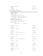
Interface : InLoop0 Cost : 0
Destination: 4::/64 Protocol :
Direct
NextHop : 4::1 Preference: 0
Interface : Vlan400 Cost : 0
Destination: 4::1/128 Protocol :
Direct
NextHop : ::1 Preference: 0
Interface : InLoop0 Cost : 0
Destination: FE80::/10 Protocol :
Direct
NextHop : :: Preference: 0
Interface : NULL0 Cost : 0
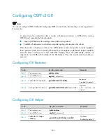
Configuring OSPFv3 GR
Network requirements
•
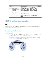
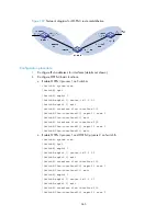
As shown in Figure 110, Switch A, Switch B, and Switch C that belong to the same AS and
the same OSPFv3 routing domain are GR capable.
•
Switch A acts as the GR Restarter. Switch B and Switch C are the GR Helpers, and
synchronize their LSDBs with Switch A through OOB communication of GR.
Figure 110
Network diagram for OSPFv3 GR configuration
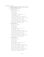
Configuration procedure
1.
Configure IPv6 addresses for interfaces (details not shown).
2.
Configure OSPFv3 basic functions.
a.
On Switch A, enable OSPFv3 process 1, enable GR, and set the router ID to 1.1.1.1.
<SwitchA> system-view
Summary of Contents for S9500E Series
Page 435: ...435 ...

