2-16
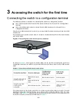
To ground the switch by using a grounding strip:
1.
Attach the two-hole grounding lug of the grounding cable to the grounding point on the chassis.
For more information, see "
Connecting the grounding cable to the chassis
."
2.
Remove the hex nut of a grounding post on the grounding strip.
3.
Attach the ring terminal at the other end of the grounding cable to the grounding post on the
grounding strip, and secure the ring terminal to the grounding post with the hex nut.
Figure2-16 Connecting the grounding cable to a grounding strip
(1) Hex nut
(2) Ring terminal
(3) Grounding post
(4) Grounding strip
Installing/removing fan modules
CAUTION:
The switch has five fan module slots. For adequate heat dissipation, follow these guidelines:
•
The switch comes with the fan module slots empty. As a best practice for adequate heat
dissipation of the switch, fully configure the switch with fan modules of the same model. If the
number of installed fan modules is less than the minimum required number, the device will output
an error message and does not power up.
•
Make sure each slot has a module or filler panel installed when the switch is operating.
•
If multiple fan modules fail on the operating switch, do not remove the fan modules at the same
time. Replace the fan modules one after another and finish replacing a fan module within 3
minutes.
CAUTION:
•
Do not touch any bare cables or terminals on the fan module.
•
Do not place the fan module in a wet area, and prevent liquid from entering into the fan module.
•
When an internal circuit or component of the fan module fails, contact H3C Support. Do not
remove any component from the fan module yourself.
The switch uses a front-rear air aisle and supports the FAN-80B-1-B fan module. The FAN-80B-1-B
fan module provides port side-intake and power supply side-exhaust airflow and its handle is red.
Summary of Contents for S9820-8C-SAN
Page 37: ...3 30...


