4
Table1-3 Harmful gas limits in an equipment room
Gas
Max. (mg/m
3
)
SO
2
0.2
H
2
S
0.006
NH
3
0.05
Cl
2
0.01
NO
2
0.04
Cooling system
For adequate cooling of the firewall, follow these guidelines:
•
Plan the firewall installation position for the airflow direction of the firewall to match the
ventilation designs at the installation site.
•
Reserve a minimum clearance of 80 mm (3.15 in) around the inlet and outlet air vents.
•
Make sure the installation site has a good cooling system.
•
When installing the firewall in a standard 19-inch rack, reserve a distance of 1U (44.45 mm, or
1.75 in) between the chassis and other devices.
The F1000-AI-05 firewall cools itself naturally.
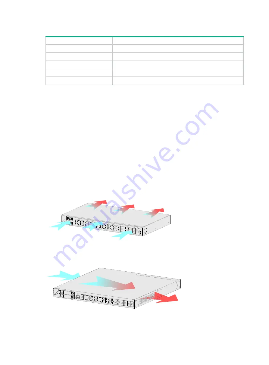
The F1000-AI-15 firewall provides front side-intake and rear side-exhaust airflow for heat dissipation.
The F1000-AI-25, F1000-AI-35, F1000-AI-55, F1000-AI-65, and F1000-AI-75 firewalls provide left
side-intake and right side-exhaust airflow for heat dissipation.
Figure1-2 Airflow through the F1000-AI-15 firewall chassis
Figure1-3 Airflow through the F1000-AI-25/F1000-AI-35/F1000-AI-55/F1000-AI-65/F1000-AI-75
firewall chassis


