Installation Manual
H3C SecPath F1000-E Firewall
Chapter 4 Installing the Firewall
4-13
III. Connection procedure
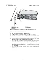
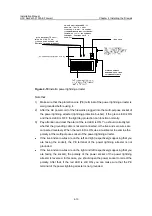
Follow these steps to connect the AC power cord:
1) Make sure that the PGND terminal is securely connected to the ground.
2) Turn the firewall power switch to the OFF position.
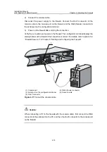
3) Connect one end of the supplied AC power cord to the power socket on the firewall,
and the other end to the power supply.
4) Turn the firewall power switch to the ON position.
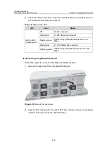
5) Check the status of the PWR LED on the front panel of the firewall. For the status
of the power LED, see Table 4-3.
Table 4-3
Status of the power LED
Color
Status
OFF
No power supply is available.
ON
The power module works abnormally.
(1)
(2)
(3)
(4)
(5)
(6)
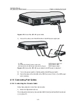
(1) Bail latch holder
(2) AC power connector
(3) Power switch
(4) AC power socket (100 V to 240V; 50/60Hz; 2.5A)
(5) Bail latch
(6) AC power cord
Figure 4-12
Connect the AC power cord
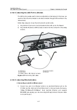
4.9.3 Connecting the RPS DC Power Cable
Follow these steps to connect the RPS DC power cable:
1) Make sure that the power switch on the firewall and the RPS input power switch
are both off.
2) Rip off the adhesive tape from the RPS socket.
3) Loosen the screws on the RPS blank panel with a Phillips screw.

