Installation Manual
H3C SecPath F1000-E Firewall
Chapter 4 Installing the Firewall
4-20
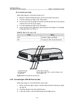
Table 4-5
Status of the SFP LED
LED
Color
Status
Off
No optical fiber link is present.
Solid green
An optical fiber link is present.
Flashing green Data is being transmitted/received.
SFP0 to SFP3
(yellow/green)
Solid yellow
The optical fiber cable fails to be detected.
Note that:
z
Avoid excessively bending optical fiber cables, with the curvature radius less than
10 cm (3.9 in.).
z
Ensure that the Tx and Rx ports of the SFP module are connected correctly.
z
Keep the end-faces of optical fiber cables clean.
Caution:
z
Never stare into an open optical Ethernet port, because invisible rays may be
emitted from the optical Ethernet port.
z
Cover the dust cover if no optical fiber connector is connected to the optical Ethernet
port.
4.10.4 Connecting a 4GBE/8GBE interface module cable
You can use a straight-through cable or crossover cable to connect a
2GBE/4GBE/8GBE interface module cable. Follow these steps to connect a
2GBE/4GBE/8GBE interface module cable:
1) Power off the firewall and then install the module into the corresponding interface
module slot. For the installation of a 4GBE/8GBE interface module, refer to section
7.6.1 “Installing HIM” in Chapter 7 “Maintaining Hardware”.
2) Use a straight-through or crossover network cable to connect an interface.
z
To connect the firewall to a PC or another firewall, use a crossover cable. Connect
one end of the network cable to the Ethernet interface of the 4GBE/8GBE interface
module, and the other end to the Ethernet port on the PC or firewall.
z
To connect the firewall to a hub or a LAN switch, use a straight-through cable.
Connect one end of the network cable to the Ethernet interface of the 4GBE/8GBE
interface module, and the other end to the Ethernet port on the hub or LAN switch.
3) Check the following after connection:

