Installation Manual
H3C SecPath F1000-E Firewall
Chapter 5 Starting and Configuring the Firewall
5-5
Warning:
Before powering on the firewall, locate the position of the power switch for the
equipment room where you will operate so that you can switch off the power supply
promptly in case of any accident
5.2.2 Powering On the Firewall
z
Turn on the power source.
z
Turn on the power switch on the firewall.
5.2.3 Checklist/Operations after Firewall Power-On
After powering on the firewall, check that:
1)
The LEDs on the front panel are normal.
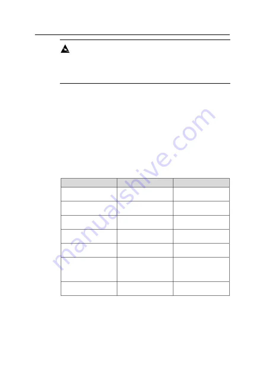
The following table describes normal LED states after the firewall is powered on.
Table 5-2
Normal LED states after firewall power-on
LED
State
Meaning
PWR (green)
ON
The power module is
working power normally.
RPS (yellow/green)
Solid green
Both the AC input and DC
output are normal.
SLOT1 (green)
ON
The module in slot 1 is
running normally.
SLOT2 (green)
ON
The module in slot 2 is
running normally.
SYS (green)
Slow flashing (1 Hz)
The system is working
normally.
CF (green)
Solid green
The host detects that the
external CF card works
normally. In this state, you
can remove the CF card.
USB1 (green)
OFF
The firewall is not
connected with a host.
2)
The fans work normally.
3)
The buzzer beeps at power-on.

