6
•
Install a power lightning arrester at the input end of the power module to enhance the lightning
protection capability of the power module.
Power supply
Verify that the power system at the installation site meets the power requirements of the device,
including the power input method and rated input voltage. For the power module specifications, see
"Appendix A Chassis views and technical specifications."
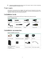
Installation tools
No installation tools are provided with the device. Prepare them yourself as required.
Figure 3 Installation tools
Crimping tool
Phillips screwdriver
Needle-nose pliers
Wire-stripping pliers
ESD wrist strap
Flathead screwdriver
Marker
Diagonal pliers
Installation accessories
Figure 4 Installation accessories
Grounding cable
M6 screw (user supplied)
Cage nut (user
supplied)
M4 screw
Front mounting bracket
with a cable
management bracket
Rubber feet
Power cord retainer
Cable tie (user supplied)


