background image


Installation quick start 

This quick start guide provides basic instructions for installing an M9000 multiservice gateway. For more 

detailed installation procedures, see 

H3C SecPath M9000 Multi Service Security Gateway Series 

Installation Guide

Confirming installation preparations 

Before you install an M9000 multiservice security gateway, verify that: 


A 19-inch rack is ready for use when you install the gateway to a rack. For how to install a rack, see 
the rack installation guide. 


The rack is sturdy and securely grounded. 


No debris exists inside or around the rack. 


Choose a correct rack mounting position for the gateway. Make sure the heaviest device is placed 
at the bottom of the rack. 


The total height of the gateways to be installed is no higher than the available installation height of 
the rack and enough clearance is reserved for cable routing. 


The gateway is ready for installation and has been carried to a place near the rack and convenient 
for moving. 

Installing the gateway 

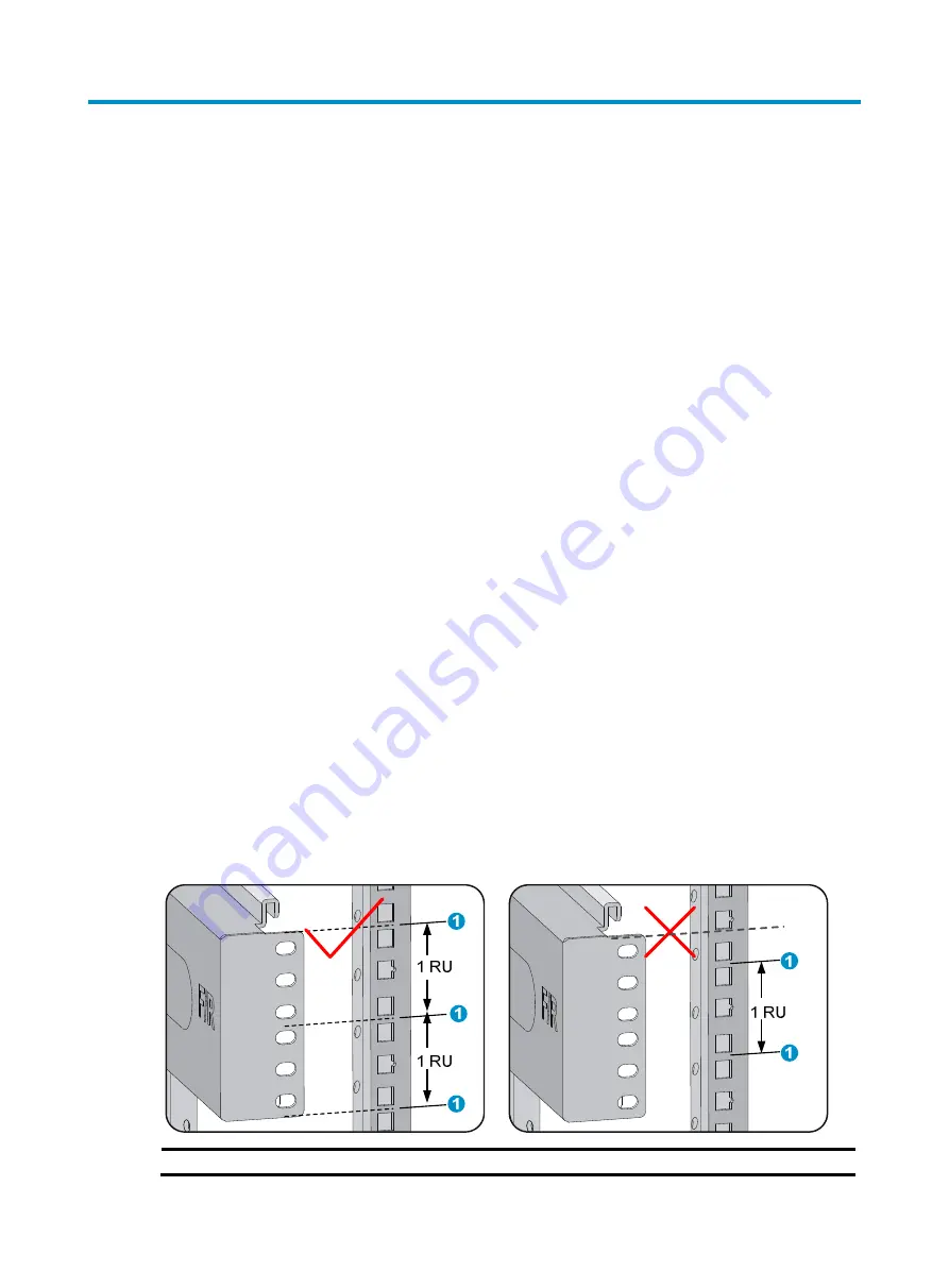
Before installing the gateway, make sure the bottom edge of the slide rail or rack shelf aligns with the 

middle of the narrower metal area between holes, as shown in 

Figure 1

One rack unit has three holes, the middle of which is an auxiliary installation hole, and the other two are 
standard installation holes. You can distinguish them by the space between each two holes. The space 

between a standard installation hole and an auxiliary installation hole is wider than that between two 

adjacent standard installation holes. 

Figure 1


Locating the rack position for installing slide rails 


(1) Middle of the narrower metal area between holes


Summary of Contents for SecPath M9000 Series

Page 1: ...H3C SecPath M9000 Multi Service Security Gateway Series Installation Quick Start New H3C Technologies Co Ltd http www h3c com hk Document version 6PW104 20170414...

Page 2: ...her trademarks that may be mentioned in this manual are the property of their respective owners Notice The information in this document is subject to change without notice Every effort has been made i...

Page 3: ...rackets 4 Mounting the gateway to the rack 5 Grounding the gateway 6 Installing FRUs 6 Attaching an ESD preventive wrist strap 6 Installing MPUs LPUs switching fabric modules 7 Installing a power modu...

Page 4: ...he gateways to be installed is no higher than the available installation height of the rack and enough clearance is reserved for cable routing The gateway is ready for installation and has been carrie...

Page 5: ...cage nut 3 Install cage nuts on the square holes on each rack post Figure 2 Installing cage nuts M9006 as an example Installing cable management brackets Cable management brackets signal cable and pow...

Page 6: ...milar procedure For more information see Figure 4 To install a cable management bracket 1 Unpack the cable management brackets 2 Attach the cable management bracket to the chassis and align the screws...

Page 7: ...art of the chassis Installing mounting brackets Marks L and R are printed inside the mounting brackets to distinguish between the left and right mounting brackets To install the mounting brackets face...

Page 8: ...the gateway on the slide rails or rack shelf and slide the gateway along the slide rails until the mounting brackets on the gateway touch the front rack posts The handle of an M9006 is located at the...

Page 9: ...e dual hole terminals of the grounding cable into the grounding holes of the chassis 4 Connect the ring terminal of the grounding cable to the grounding post of the grounding strip and fasten the grou...

Page 10: ...rds in this document These cards are either horizontally oriented or vertically oriented When installing a card in a horizontal slot make sure its PCB faces up When installing a card in a vertical slo...

Page 11: ...on only To install the power module 1 Use a Phillips screwdriver to loosen the captive screws on the blank filler panel if any to remove the blank filler panel 2 Unpack the power module 3 Follow the i...

Page 12: ...G Before you connect the power cable make sure the circuit breaker on the power cable is switched off To connect the power cable 1 Plug the power cable into the power receptacle of the power module 2...

Page 13: ...the power receptacle of the power module 2 Fasten the screw to secure the power cable Figure 13 Connecting the power cable on an M9010 1 Insert the power cable plug into the power module 2 Fasten the...

Page 14: ...s catch in the slot For a QSFP module that uses a plastic pull latch skip this step QSFP modules use either a metal or plastic pull latch They are installed in the same way except that you must pivot...

Page 15: ...en you disconnect the cable first disconnect from the gateway Obtaining documentation To access the most up to date H3C product documentation on the H3C website at www h3c com hk 1 Go to http www h3c...

Reviews: