21
Installing a CFP module
CAUTION:
•
Read the following instructions before installing a CFP module. Failure to follow these
instructions might cause damage to the CFP module.
•
Do not remove the dust plug from the CFP module before connecting an optical fiber.
•
Before installing a CFP module, remove the optical fiber, if any, from it.
To install a CFP module:
1.
Wear an ESD wrist strap and make sure it makes good skin contact and is correctly grounded.
For more information, see "
2.
Unpack the CFP module. Do not touch the golden finger of the module.
3.
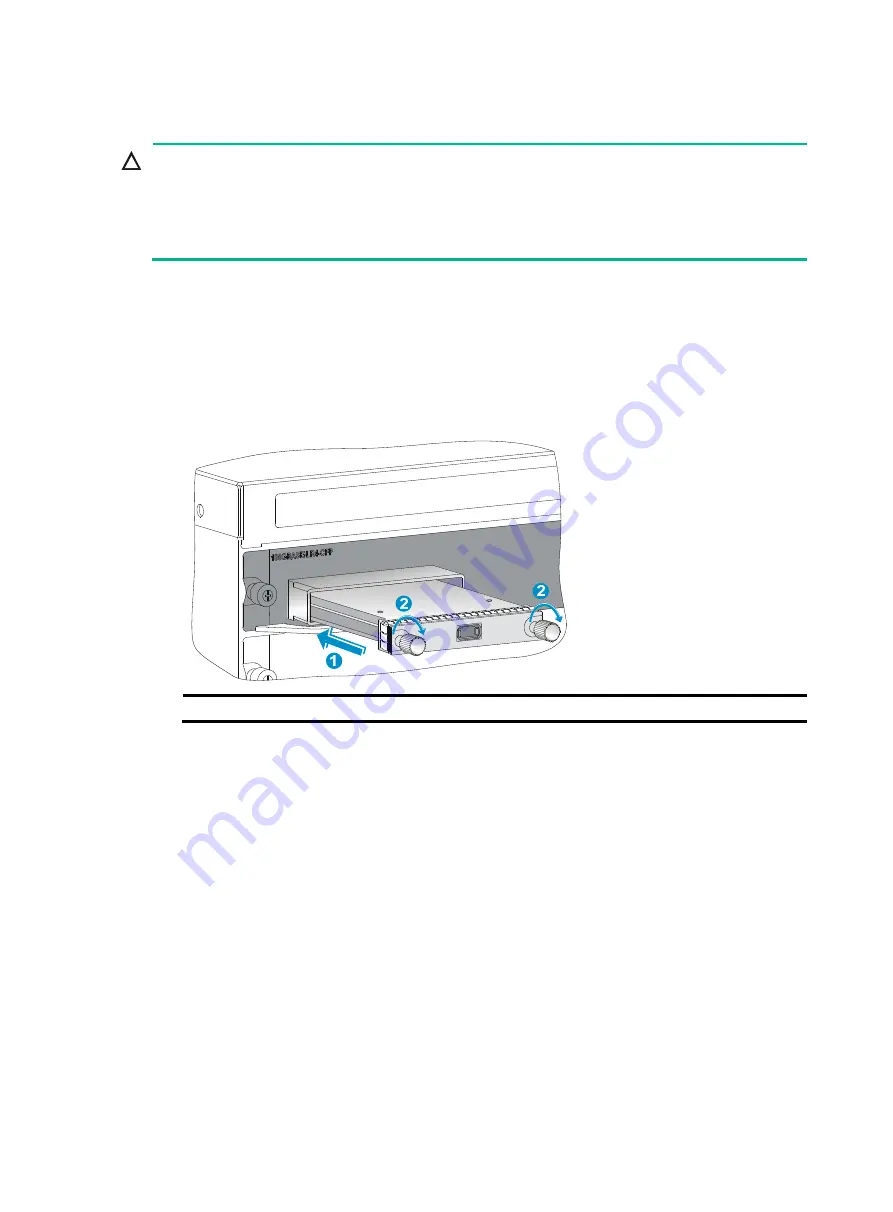
Gently push the CFP module into the slot until it has firm contact with the slot, and then fasten
the captive screws on the CFP module.
Figure 21 Installing a CFP module
(1) Gently push the CFP module into the slot
(2) Fasten the captive screws on the CFP module
4.
Connect the optical fiber to the CFP module. For information about connecting optical fibers,
see "
Connecting networking cables
Connecting twisted pair cables
The 10/100Base-TX ports, 1000Base-T ports, and 10GBase-T ports on your gateway use RJ-45
connectors and support MDI/MDI-X auto-sensing. Use category-6A or category-7 twisted pair cables
to connect 10GBase-T ports and category-5 or above to connect other ports. For more information
about twisted pair cables, see "
To connect a 10/100Base-TX, a 1000Base-T port, or a 10GBase-T port to a peer device:
1.
Plug one end of a twisted pair cable into the RJ-45 Ethernet port on the gateway.
2.
Plug the other end of the twisted pair cable into the RJ-45 Ethernet port of the network access
device.
3.
Examine the port LEDs to verify the connection after the gateway is powered on.
For more information about the LED status, see "
."


