background image


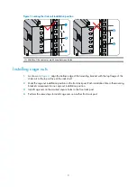
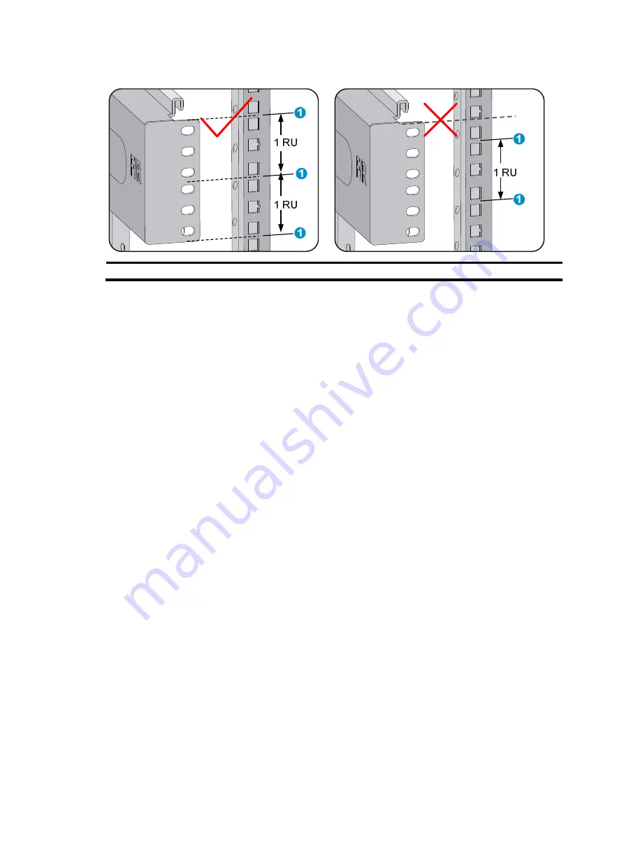
Figure 1


Locating the slide rail installation position 


(1) Middle of the narrower metal area between holes 


Installing cage nuts 

1.


As shown in 

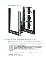
Figure 2

, align the bottom edge of the mounting bracket with the top flange of the 

slide rail or the top surface of the rack shelf. 

2.


Mark the cage nut installation position on the front rack post. Each installation hole in the mounting 
bracket corresponds to one cage nut installation position. 

3.


Install cage nuts on the marked square holes in the front rack post. 

4.


Perform the same steps to install cage nuts on another front rack post. 

Summary of Contents for SecPath T9000 IPS Series

Page 1: ...H3C SecPath T9000 Intrusion Prevention System Series Installation Quick Start New H3C Technologies Co Ltd http www h3c com hk Document version 5PW101 20170411...

Page 2: ...her trademarks that may be mentioned in this manual are the property of their respective owners Notice The information in this document is subject to change without notice Every effort has been made i...

Page 3: ...ackets to the IPS 4 Attaching the mounting brackets to the IPS 6 Installing the IPS in the rack 7 Grounding the IPS 8 Installing FRUs 8 Attaching an ESD wrist strap 8 Installing cards 9 Installing pow...

Page 4: ...eserved for cable routing If you are to install multiple devices in the rack place the heaviest device at the rack bottom Installing the IPS IMPORTANT The IPS is heavy H3C recommends that you install...

Page 5: ...bracket with the top flange of the slide rail or the top surface of the rack shelf 2 Mark the cage nut installation position on the front rack post Each installation hole in the mounting bracket corr...

Page 6: ...cord management bracket for them For the T9010 IPS the signal cable management bracket installation position is at the upper part of the chassis The power cord management bracket installation position...

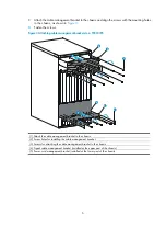
Page 7: ...management brackets to a T9010 IPS 1 Attach the cable management bracket to the chassis 2 Screw holes for installing the cable management bracket 3 Screws for attaching the cable management bracket to...

Page 8: ...ed at the lower part of the chassis Attaching the mounting brackets to the IPS Identify the left and right mounting brackets by their marks L and R Attach the left and right mounting brackets to the t...

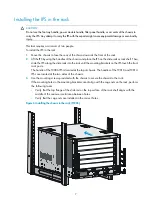
Page 9: ...de the IPS along the slide rails into the rack until the mounting brackets on the IPS touch the front rack posts The handle of the T9006 IPS is located at the top of chassis The handles of the T9010 a...

Page 10: ...ounding screws to attach the two hole grounding lug to the grounding point on the chassis 4 Use the grounding screw to attach the ring terminal of the grounding cable to the grounding terminal on the...

Page 11: ...s are either horizontally oriented or vertically oriented When installing a card in a horizontal slot make sure its PCB faces up When installing a card in a vertical slot make sure its PCB faces left...

Page 12: ...anel installed use a Phillips screwdriver to loosen the captive screws on the filler panel and remove the filler panel 2 Unpack the power module 3 Follow the installation graph printed on the filler p...

Page 13: ...ord WARNING Before you connect a power cord make sure the circuit breaker at the power input end is switched off To connect an AC power cord 1 Plug the AC power cord connector into the power receptacl...

Page 14: ...cle of the power module 2 Fasten the screw on the connector to secure the power cord in place Figure 13 Connecting a DC power cord T9010 1 Plug the DC power cord connector into the power receptacle of...

Page 15: ...er module gently push the module into the slot until you feel that the bottom spring tab catch in the slot For a QSFP module that uses a plastic pull latch skip this step Figure 14 Installing an XFP S...

Page 16: ...ting switch first connect the PC end To disconnect a PC from an operating switch first disconnect the switch end Obtaining documentation To access the most up to date H3C product documentation on the...

Page 17: ...G Grounding the IPS 8 I Installing FRUs 8 Installing the IPS 2 L Logging in to the IPS 13 O Obtaining documentation 14 P Preparing for installation 2 Copyright 2017 New H3C Technologies Co Ltd For mor...

Reviews: