background image

Installation Manual 
H3C SecPath V1000-A Security Gateway 

Chapter 4  Booting and Configuration


4-1 

Chapter 4  Booting and Configuration 

4.1  Booting 

You can only configure the security gateway through the console port when you use it 
for the first time. 

4.1.1  Setting up a Configuration Environment 

I. Connecting the device to a console terminal 

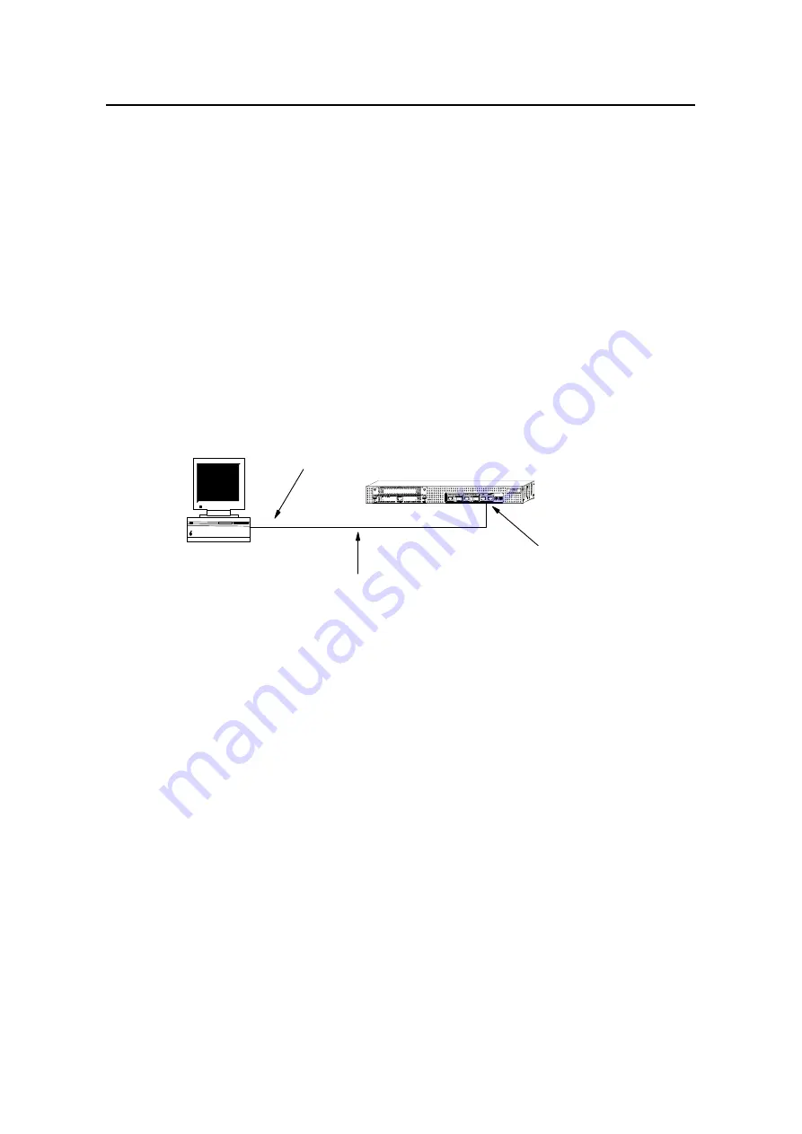
Connect the RJ45 connector of the console cable to the console port on the security 
gateway and the DB9 connector to the serial port on the console terminal, as shown in 
Figure 4-1. 

RS232 serial interface

Console cable

PC

H3C SecPath V1000-A

Console port


Figure 4-1 

Local configuration through the console port 

II. Setting terminal parameters 

Follow these steps to set terminal parameters on the console terminal, a PC running 
Windows98 for example: 

Step 1: Start the PC and select [Start/Programs/Accessories/Communications/HyperTe
rminal].  

The HyperTerminal window displays the Connection Description dialog box, as shown 
in Figure 4-2

Summary of Contents for SecPath V1000-A

Page 1: ...H3C SecPath V1000 A Security Gateway Installation Manual Hangzhou H3C Technologies Co Ltd http www h3c com Manual Version T2 08044E 20070622 C 1 03 ...

Page 2: ...m InnoVision and HUASAN are trademarks of Hangzhou H3C Technologies Co Ltd All other trademarks that may be mentioned in this manual are the property of their respective owners Notice The information in this document is subject to change without notice Every effort has been made in the preparation of this document to ensure accuracy of the contents but all statements information and recommendation...

Page 3: ...view usage description and configuration example H3C SecPath Series Security Products Web Based Configuration Manual It directs users to configure the H3C SecPath Series Firewalls in Web mode Organization H3C SecPath V1000 A Security Gateway Installation Manual is organized as follows Chapter Contents 1 Product Overview Profiles the system characteristics and applications Product appearance and sy...

Page 4: ...conventions Convention Description Boldface The keywords of a command line are in Boldface italic Command arguments are in italic Items keywords or arguments in square brackets are optional x y Alternative items are grouped in braces and separated by vertical bars One is selected x y Optional alternative items are grouped in square brackets and separated by vertical bars One or none is selected x ...

Page 5: ...e Create Folder III Symbols Convention Description Warning Means reader be extremely careful Improper operation may cause bodily injury Caution Means reader be careful Improper operation may cause data loss or damage to equipment Note Means a complementary description Environmental Protection This product has been designed to comply with the requirements on environmental protection For the proper ...

Page 6: ...ing Rack 2 3 2 2 Safety Precautions 2 3 2 3 Unpacking Check 2 4 2 4 Tools Meters and Devices 2 4 Chapter 3 Hardware Installation 3 1 3 1 Installation Procedures 3 1 3 2 Mounting the Device 3 2 3 2 1 Tabletop Workbench Mounting the Device 3 2 3 2 2 Rack Mounting the Device 3 2 3 3 Installing an MIM 3 3 3 4 Connecting the Grounding Wire 3 3 3 5 Connecting to the Console Terminal 3 4 3 6 Connecting a...

Page 7: ... 2 Removing a DDR SDRAM 6 5 6 3 3 Installing a DDR SDRAM 6 6 6 4 Closing the Chassis Cover 6 6 6 5 Replacing an MIM 6 7 Chapter 7 Troubleshooting 7 1 7 1 Troubleshooting the Power System 7 1 7 2 Troubleshooting the Configuration System 7 1 7 3 Troubleshooting the Software Upgrade 7 2 Chapter 8 Multifunctional Interface Modules 8 1 8 1 Multifunctional Interface Module Options 8 1 8 2 Installing and...

Page 8: ...ameters 4 3 Figure 4 5 Settings tab 4 3 Figure 5 1 Send File dialog box 5 4 Figure 5 2 Sending File interface 5 4 Figure 5 3 Setting up an environment for local uploading downloading using FTP 5 9 Figure 5 4 Setting up an environment for remote uploading downloading using FTP 5 10 Figure 6 1 Opening the chassis 6 2 Figure 6 2 DDR SDRAM maintenance flow 6 3 Figure 6 3 The position of the DDR SDRAMs...

Page 9: ...SecPath V1000 A Security Gateway List of Figures iv Figure 8 10 2GBE module 8 9 Figure 8 11 1GBE module panel 8 9 Figure 8 12 2GBE module panel 8 9 Figure 8 13 Ethernet cable 8 10 Figure 8 14 Category 5 twisted pair cable 8 11 ...

Page 10: ... optical interfaces 1 6 Table 2 1 Temperature Humidity requirements in the equipment room 2 1 Table 2 2 Limit to the content of dust in an equipment room 2 2 Table 2 3 Limits on the contents of harmful gases in the equipment room 2 2 Table 3 1 Dimensions of the SecPath V1000 A 3 2 Table 6 1 Memory specifications 6 4 Table 8 1 Attributes of the 1FE and 2FE modules 8 4 Table 8 2 LED behavior 8 5 Tab...

Page 11: ...ltiple Virtual Private Network VPN services such as Layer 2 Tunneling Protocol L2TP VPN IP Security IPsec VPN Generic Routing Encapsulation GRE VPN and Dynamic VPN It can connect to remote users through dial up leased line VLAN or tunnel thus building VPNs in the form of internet intranet or access network The security gateway brings together the technologies of firewall AAA Network Address Transl...

Page 12: ...ks over the Internet z Virtual Router Redundancy Protocol VRRP to provide backup in case of communication line or equipment failures This effectively enhances network robustness and reliability z Deeper application recognition DAR to recognize and classify packets more deeply thus enhancing the control over data flows z Object oriented management simplifying configuration management and improving ...

Page 13: ...modes 1 auxiliary port AUX 1 console port CON Boot ROM 512 KB DDR SDRAM Default 512 MB Max 1 GB Flash Default 16 MB Max 32 MB Dimensions W X D X H 436 x 430 x 44 mm 17 2 x 16 9 x 1 7 in excluding the rubber feet Input power AC AC Rated voltage range 100 VAC to 240 VAC 50 60 Hz Max voltage range 90 VAC to 264 VAC 50 60 Hz Rated current 1 0 A Max power 57 W Operating temperature 0 to 40 C 32 F to 10...

Page 14: ...the device PWR1 PSU LED OFF means the PWR1 is not supplying power to the device ON means the PWR1 is supplying power to the device SYS System operating status LED On means the system is operating normally OFF means the system is operating abnormally ACT MIM in position status LED Blinking means the MIM is operating normally OFF means the MIM is operating abnormally LINK GE interface LED ON means a...

Page 15: ... electrical interface one in use at a time The electrical interface uses the RJ45 connector and the optical interface uses the Small Form Factor Pluggable SFP module Five 1000Base FX SFP optical transceiver options are available for the SecPath V1000 A multi mode short haul 850 nm single mode medium haul 1310 nm single mode long haul 1310 nm single mode long haul 1550 nm and single mode ultra long...

Page 16: ...4 86 mi 40 km 24 86 mi 70 km 43 5 mi Central wavelength 850 nm 1310 nm 1310 nm 1550 nm 1550 nm Min 9 5 dBm 9 dBm 2 dBm 4 dBm 4 dBm Transmi tter optical power Max 0 dBm 3 dBm 5 dBm 1 dBm 2 dBm Receiver sensitivity 17 dBm 20 dBm 23 dBm 21 dBm 22 dBm Operating mode 1000 Mbps Full duplex Frame format Ethernet_II Ethernet_SNAP Note z When using optical transceivers select those that have been approved ...

Page 17: ...ast Ethernet interface module 1FE z 2 port 10Base T 100Base TX Fast Ethernet interface module 2FE z 1 port 10Base T 100Base T 1000Base TX Ethernet interface module 1GBE z 2 port 10Base T 100Base T 1000Base TX Ethernet interface module 2GBE For more information on the MIMs see Chapter 8 Multifunctional Interface Module ...

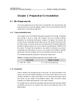
Page 18: ...ing the CMOS circuit of the product The higher the temperature is the greater the damage to your device Long lasting high temperature can speed up the aging of the insulation materials greatly lower the device reliability and hence significantly shorten its service life The following table lists the temperature and humidity requirements Table 2 1 Temperature Humidity requirements in the equipment ...

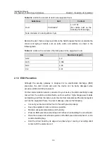
Page 19: ...ESD preventive the card circuits and even the device can be badly damaged when excessive static electricity is present On the communication network connected to your device the static electricity mainly comes from the outside electrical fields such as outdoor high voltage power cables and lightning and from the indoor environments floor materials and the internal system such as the equipment frame...

Page 20: ...istant your device can get damaged when excessive lightning is present To protect your device against lightning z Ensure the chassis is connected to the earth ground z Ensure the earth point of the power socket is well connected to the earth ground z Add a lightning arrester onto the front end of the power input to better protect the power supply from lightning strikes 2 1 6 Mounting Rack When ins...

Page 21: ... Tx port or the optical connector connected to it z You are recommended to use Uninterrupted Power Supply UPS for the security gateway 2 3 Unpacking Check Check the arrived shipment against the packing list making sure all the items are included and in good condition Contact your agent for shortage or wrong delivery 2 4 Tools Meters and Devices I Tools z Phillips screwdriver z Flat blade screwdriv...

Page 22: ...ct the grounding wires Connect the power cord Connect the Security gateway to a terminal for configuration Verify the installation Power up Normal Install the MIM interface Connect the Ethernet Verify the installation Connect the power cord Power up End Troubleshoot Power down Power down the remove the power cord Security gateway and Install the Security gateway Figure 3 1 Installation procedure ...

Page 23: ...r adequate ventilation z Do not place any heavy object on the device 3 2 2 Rack Mounting the Device The security gateway can be placed in a 19 inch standard rack The following table shows its dimensions Table 3 1 Dimensions of the SecPath V1000 A Model Dimensions SecPath V1000 A W X D X H 436 x 430 x 44 mm 17 2 x 16 9 x 1 7 in excluding the rubber feet Follow these steps to install the SecPath V10...

Page 24: ...unding Wire Caution When installing or using your security gateway properly connect the grounding wire for lightning protection and anti interference The security gateway provides a grounding screw which must be connected to the earth ground properly to safely channel the faradic current and leakage electricity to the ground and have the device less susceptible to electromagnetic interference EMI ...

Page 25: ...lightning protection make sure that your security gateway has a good ground connection when it is operating 3 5 Connecting to the Console Terminal I Console port On the security gateway one RS232 asynchronous serial console port is available for you to configure the device For the attributes of the console port refer to the section 1 2 4 Attributes of the Fixed Interfaces II Console cable Console ...

Page 26: ...e connection and power up the devices The console terminal shows the startup information of the security gateway if the connection is correct For details see Chapter 4 Booting and Configuration 3 6 Connecting an Ethernet Interface I Introduction to the Ethernet interface The SecPath V1000 A provides two fixed 10 100 1000 Mbps auto sensing GE interfaces each providing an optical interface and an el...

Page 27: ...ber connectors All the optical transceivers are hot swappable Note A fiber connector as defined by the International Telecommunications Union ITU is a passive component that connects two or more fiber optic segments stably but not permanently Fiber connectors are indispensable to an optical communication system making it possible to connect and disconnect optical channels Following are several fib...

Page 28: ...nnect the Ethernet electrical port Caution Read the mark above the port to be connected carefully making sure it is the correct port Step 1 Connect one end of the Ethernet cable to the electrical port of the 10 100 1000 Mbps Ethernet 1 and the other end to the peer device Step 2 Check the status of the LINK LED for the Ethernet 1 interface ON means the Rx link is present OFF means no Rx link is pr...

Page 29: ...n the Tx port on the security gateway and the Rx port on the peer device Step 2 Power up the SecPath V1000 A and check the status of the LINK LED of the Ethernet 1 interface On means the Rx link is present OFF means no Rx link is present check the line for the cause 3 7 Connecting a PSU The security gateway is AC powered Note If both PSUs are in use they can back up each other I AC input PSU AC in...

Page 30: ...t PWR0 on the left rear of the chassis and the other end to the AC mains supply Step 3 Repeat Step 2 to connect the PWR1 Skip this step if you use only one PSU Step 4 Place the PWR0 switch into the ON position Step 5 Place the PWR1 switch to the ON position Skip this step if you use only PWR0 Step 6 Check that the PWR0 and PWR1 LEDs on the front panel light ON means the power connections are corre...

Page 31: ...able to the console port on the security gateway and the DB9 connector to the serial port on the console terminal as shown in Figure 4 1 RS232 serial interface Console cable PC H3C SecPath V1000 A Console port Figure 4 1 Local configuration through the console port II Setting terminal parameters Follow these steps to set terminal parameters on the console terminal a PC running Windows98 for exampl...

Page 32: ... shown in Figure 4 3 pops up Step 3 Select the serial port to be used from the Connect Using dropdown menu The serial port must be the same port connected by the console cable Figure 4 3 Setting the connection port Step 5 Click OK The Port Settings tab shown in Figure 4 4 appears and you can set serial port parameters Set the following parameters z Baud rate 9600 z Databit 8 z Parity check none z ...

Page 33: ... 4 Setting communications parameters Step 6 Click OK The HyperTerminal dialogue box appears Step 7 Select Properties Step 8 In the Properties dialog box select the Settings tab as shown in Figure 4 5 Step 9 Select VT100 or Auto detect in the Emulation dropdown menu Step 10 Click OK Figure 4 5 Settings tab ...

Page 34: ... device into the ON position III Checking Operating after power up After powering up the security gateway check that z The ventilation system is operating well After powering up the security gateway you can hear the sound of the fan blade spinning and feel the airflow when you put your hands close to the air vents z The LEDs on the front panel of the chassis are in normal state See the section 1 2...

Page 35: ...ress Ctrl B to enter Boot Menu Press Ctrl B to enter the Boot menu Otherwise the system starts decompressing the program Note To enter the Boot Menu you must press Ctrl B within three seconds after the prompt Press Ctrl B to Enter Boot Menu appears The system starts decompression and initialization and displays System is starting Number 1 memory block start from address 0x23000000 length 0xd000000...

Page 36: ... corresponding product 4 2 2 Command Line Interface I Features of the CLI The CLI of the security gateway offers lots of configuration commands for you to configure and manage the security gateway The CLI allows you to z Configure the device through the console port at the local z Telnet to access and manage the local and remote devices z Get online help whenever you enter z Test network connectiv...

Page 37: ...gure 4 1 and then boot the security gateway Press Ctrl B when the system prompts Press Ctrl B to enter Boot Menu The system displays Please input Boot ROM password Caution z Press Ctrl B within three seconds after the prompt Press Ctrl B to Enter Boot Menu appears to access the Boot Menu Otherwise the system starts decompressing the program z If you want to access the Boot menu after the system st...

Page 38: ...ram for backward compatibility If you fails to upgrade the software because the system decides that you are using an invalid version even when the correct version is used you can use the option 7 to ignore the version check during a software upgrading Note that this option works only once when you select it The system resumes version check after you reboot the security gateway II Boot ROM submenu ...

Page 39: ...t Menu and enter 1 to download an application program using XModem The security gateway supports the following downloading speeds Downloading application program from serial Please choose your download speed 1 9600 bps 2 19200 bps 3 38400 bps 4 57600 bps 5 115200 bps 6 Exit to Main Menu Enter your choice 1 6 Step 2 Choose an appropriate downloading speed for example 115200 bps by entering 5 The fo...

Page 40: ...gure 5 1 Send File dialog box Step 5 Click Browse Select the application file to be downloaded and set protocol to XModem Click Send The following interface pops up Figure 5 2 Sending File interface Step 6 After completing the downloading the system begins writing data to the Flash and then displays the following information in the terminal interface indicating the completion of the downloading Do...

Page 41: ...d in the section 5 1 2 Upgrading an application program Caution You cannot restore the Boot ROM program on site if you fail to upgrade the entire Boot ROM program Therefore you must not upgrade the entire Boot ROM program unless necessary and under direction of support engineers III Upgrading the extended segment of the Boot ROM Step 1 Enter the Boot Menu see the section 5 1 1 Boot Menu and select...

Page 42: ...extended segment of the Boot ROM from the Flash If faults occur to the extended segment of the Boot ROM or you upgrade it wrongly you can restore the extended segment of the Boot ROM from the Flash to the Boot ROM by taking these steps Step 1 Enter the Boot Menu see the section 5 1 1 Boot Menu and select 7 to enter the Boot ROM operation submenu Step 2 Select 3 in the operation submenu to restore ...

Page 43: ...way and enter the Boot menu see the section 5 1 1 Boot Menu Select 2 to enter the Net Port Download Menu The system displays the following message Net Port Download Menu 1 Change Net Parameter 2 Download From Net 3 Exit to Main Menu Enter your choice 1 3 1 Step 2 Select 1 to configure the network interface parameters including the interface in use and the IP address and subnet mask of the interfac...

Page 44: ...wnload Menu Saving config please wait OK Net Port Download Menu 1 Change Net Parameter 2 Download From Net 3 Exit to Main Menu Enter your choice 1 3 2 Step 4 Select 2 to download the application program using TFTP The system displays the following message Starting the TFTP download TFTP download completed File length 03598640 Writing program code to FLASH Please wait it needs a long time Please wa...

Page 45: ... SecPath V1000 A FTP Server Ethernet i 10 110 FTP Client 10 110 10 13 24 nterface 10 10 24 Figure 5 3 Setting up an environment for local uploading downloading using FTP Step 1 Connect the PC to an Ethernet interface on the security gateway Step 2 Assign an IP address 10 110 10 10 for example to the Ethernet interface on the security gateway Step 3 Assign an IP address 10 110 10 13 for example to ...

Page 46: ...mple II Enabling the FTP server Follow these steps under the direction of service engineers Step 1 Configure an authentication method Note You can configure AAA authentication as needed For more information see the section AAA and RADIUS Configurations in the Operation Manual and Command Manual of the corresponding product Step 2 Add the username and password VPNGateway local user VPNGateway VPNGa...

Page 47: ... server ready on VPNGateway at User 10 110 10 10 none Step 2 Log onto the FTP server using the username and password set on the security gateway User 10 110 10 10 none VPNGateway 331 Password required for ftp Password 230 User ftp logged in ftp Appearance of the prompt ftp indicates that you can begin uploading downloading the desired file Step 3 Upload Download the application program configurati...

Page 48: ...press the bootrom bootromfull program from the root directory in the Flash and write it to the Boot ROM After that you have completed the upgrade of Boot ROM z Download an application program configuration file ftp get Type get meaning to download local file Type the name of the application program configure file to be saved remote file Type the name of the application program configure file in th...

Page 49: ...move the power cords Step 2 Remove the interface cables from the front of the chassis except for the grounding wire Step 3 Place the security gateway on a flat table with the rear forward Use a Phillips screwdriver to remove the two captive screws securing the cover at the rear of the chassis Step 4 Undo the two captive screws securing the cover at each side of the chassis Step 5 Raise the cover t...

Page 50: ... before you open the chassis The company is not liable for any damage or consequence resulted from users operation without permission z Ensure that the security gateway has no electricity before servicing the device to avoid bodily injuries and device damages z Wear an ESD preventive wrist strap when servicing the device making sure it has good skin contact z You must use the SDRAMs provided by H3...

Page 51: ... DDR SD osition of RAM Remove the DDR SD old RAM Install the DDR SD new RAM Close the chassis Prepare the tools Start Complete h mainte ardware nance Open the chassis Locate the DDR SDRAM Remove the old DDR SDRAM Install a new DDR SDRAM Close the chassis Prepare tools Start End Open the chassis Verify the p DDR SD osition of RAM Remove the DDR SD old RAM Install the DDR SD new RAM Close the chassi...

Page 52: ...nstall a DDR SDRAM in a memory bank 6 3 1 Locating the DDR SDRAMs on the Mainboard When removing installing a DDR SDRAM make sure to identify the type of mainboard and the exact position of the DDR SDRAM See the following table for the types of memory used in the Security Gateway and the configuration Table 6 1 Memory specifications Item Specifications Memory type DDR SDRAM Max size of an identifi...

Page 53: ...DR SDRAM into a memory bank press the positioning recess into the pin in the bank 6 3 2 Removing a DDR SDRAM Step 1 Locate the DDR SDRAM to be replaced on the mainboard Step 2 Press the clips at both sides of the DDR SDRAM bank outward with appropriate pressure till the DDR SDRAM ejects from the bank Figure 6 4 Removing a DDR SDRAM Step 3 Hold the DDR SDRAM by its non conductive edge and take it o...

Page 54: ...ure 6 3 Step 2 Hold the DDR SDRAM by its non conductive top edge and place it in the desired memory bank Step 3 Exercise adequate pressure on the DDR SDRAM to press it into the bank Press the clips at both sides of the bank inward until the locking pins at the end of the clips are engaged with the semicircular recesses at the bottom of the DDR SDRAM Repeat these steps to install all the DDR SDRAMs...

Page 55: ...is direction 2 Install six screws at these places Figure 6 5 Closing the chassis cove Step 5 Tighten the six captive screws that are removed in steps 3 and 4 described in the section 6 2 Opening the Chassis Cover to secure the cover to the chassis body 6 5 Replacing an MIM For details see Chapter 8 Multifunctional Interface Modules ...

Page 56: ... not light yet after you finish the above operations 7 2 Troubleshooting the Configuration System If the security gateway is operating normally after it is powered up it displays the start up information on the console terminal If the configuration system has failed it displays illegible characters or nothing at all I No information on the terminal 1 Symptom The powered up security gateway display...

Page 57: ... different 7 3 Troubleshooting the Software Upgrade I Fault 1 1 Symptom Start the security gateway and upgrade the Comware using TFTP The system displays Net Port Download Menu 1 Change Net Parameter 2 Download From Net 3 Exit to Main Menu Enter your choice 1 3 2 Starting the TFTP download Failed to connect the tftp server Please check the network setting 2 Troubleshooting Check that z The TFTP se...

Page 58: ...ult 3 1 Symptom Start the security gateway and upgrade the Comware using TFTP The system displays Net Port Download Menu 1 Change Net Parameter 2 Download From Net 3 Exit to Main Menu Enter your choice 1 3 2 Starting the TFTP download The downloaded software is not a valid version Please download the correct version 2 Troubleshooting Check that you are downloading the correct software version Note...

Page 59: ...ase T 100Base T 1000Base TX Ethernet interface module 2GBE 8 2 Installing and Removing an MIM Caution The electromagnetic shielding EMS gaskets on the front panel of an MIM have special EMS effect for the entire security gateway So keep the gaskets intact when removing or replacing an MIM and do not damage them Before installing MIMs read Chapter 2 Preparation for Installation carefully I Tools ES...

Page 60: ... state of the ACT LED for the slot on the security gateway If the LED is flashing it means the MIM is installed correctly Figure 8 1 Installing the MIM step 1 Figure 8 2 Installing a MIM step 2 III Removing an MIM Step 1 Place the security gateway with its front facing towards you Step 2 Turn off the mains supply and remove the power cord Step 3 Remove all interface cables from the front of the ch...

Page 61: ...te normally check that z Correct interface cables are used z The interfaces are working well by reading the interface LEDs z The configurations on the MIM are validated by executing the display command 8 4 1FE 2FE Module 8 4 1 Introduction 1 2 port 10Base T 100Base TX Fast Ethernet interface module 1FE 2FE provides the communications between the security gateway and LANs The 1FE provides one 10 10...

Page 62: ...e shows the 2FE module Figure 8 4 2FE module 8 4 3 Interface Attributes The following table shows the attributes of the 1FE and 2FE modules Table 8 1 Attributes of the 1FE and 2FE modules Description Attributes 1FE module 2FE module Connector RJ45 Number of connectors 1 2 Cable type Straight through Ethernet cable Operating mode Full duplex Half duplex 10 100 Mbps auto sensing ...

Page 63: ...e panel The following table describes the LEDs on the 1FE 2FE module panel and how to read their status Table 8 2 LED behavior LED Description LINK OFF means no link is present ON means a link is present ACTIVE OFF means no packets are being transmitted received on the interface flashing means packets are being transmitted received on the interface 8 4 5 Interface Connection Cable I Ethernet cable...

Page 64: ...connectors using a category 5 twisted pair cable refer to Figure 8 8 A category 5 twisted pair cable is composed of eight wires that are identified and grouped by colors of the outer insulator Usually a solid color wire and a white solid color wire are organized in pairs But sometimes wires are also paired by color coded points Pair 1 Pair 1 Pair 1 Pair 1 Pair 1 Pair 1 Pair 1 Pair 1 Pair 1 Pair 1 ...

Page 65: ...White brown 7 8 Brown 8 Ethernet cables are divided into two categories straight through and crossover z Straight through cable The sequences of the twisted pairs crimped in the RJ 45 connectors at both ends are the same It connects a terminal device PC or router to a HUB or LAN Switch z Crossover cable The sequences of the twisted pairs crimped in the RJ 45 connectors at both ends are different I...

Page 66: ...no link is present and you should check the connection Caution Read the mark of a port carefully before you connect it a wrong connection can cause damages to the interface module and even the device 8 5 1GBE 2GBE Module 8 5 1 Introduction 1 2 port 10Base T 100Base T 1000Base TX Ethernet interface module 1GBE 2GBE can provide the communications between the SecPath V1000 A and a LAN The 1GBE 2GBE m...

Page 67: ...e attributes of the 1GBE 2GBE module Attribute 1GBE 2GBE Connector RJ 45 Number of connectors 1 2 Interface type MDI MDIX Interface standard 802 3 802 3u 802 3ab Cable type Ethernet cable Operating mode 10 100 1000 Mbps auto sensing Full half duplex autonegotiation 8 5 4 Panel and Interface LEDs Figure 8 11 and Figure 8 12 show respectively the panel of the 1GBE and 2GBE modules Figure 8 11 1GBE m...

Page 68: ... Interface Connection Cable I Ethernet cable The 1GBE 2GBE module uses a category 5 twisted pair cable with RJ 45 connectors see Figure 8 13 Pins 1 and 2 of the connectors are for transmitting data and Pins 3 and 6 are for receiving data Figure 8 13 Ethernet cable II Making an Ethernet cable To make an Ethernet cable with RJ 45 connectors using a category 5 twisted pair cable refer to Figure 8 14 ...

Page 69: ...minal device PC or router to another terminal device You can make crossover cables by yourself For the Ethernet cable pinout see Low End and Mid Range Series Routers Cable Manual 8 5 6 Connecting the Interface Cable Step 1 Plug one end of the cable to the GE port on the 1GBE 2GBE module on the SecPath V1000 A and another end to the peer device For a PC or Router use a straight through cable for a ...

Reviews: