background image

Symbols 

Convention 

Description 

 WARNING! 

An alert that calls attention to important information that if not understood or followed 
can result in personal injury. 

 CAUTION: 

An alert that calls attention to important information that if not understood or followed 
can result in data loss, data corruption, or damage to hardware or software.  

 IMPORTANT: 

An alert that calls attention to essential information. 

NOTE: 

An alert that contains additional or supplementary information. 

 TIP: 

An alert that provides helpful information. 


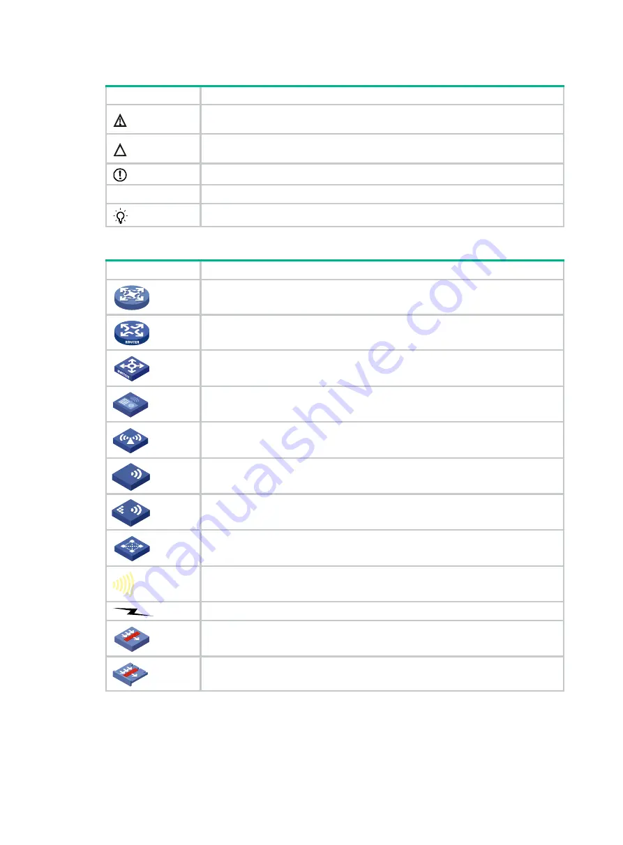
Network topology icons 

Convention 

Description 


Represents a generic network device, such as a router, switch, or firewall. 


Represents a routing-capable device, such as a router or Layer 3 switch. 


Represents a generic switch, such as a Layer 2 or Layer 3 switch, or a router that 
supports Layer 2 forwarding and other Layer 2 features. 


Represents an access controller, a unified wired-WLAN module, or the access 
controller engine on a unified wired-WLAN switch. 


Represents an access point. 


Wireless terminator unit. 


Wireless terminator. 


Represents a mesh access point. 


Represents omnidirectional signals. 


Represents directional signals. 


Represents a security product, such as a firewall, UTM, multiservice security 
gateway, or load balancing device. 


Represents a security module, such as a firewall, load balancing, NetStream, SSL 
VPN, IPS, or ACG module. 


Examples provided in this document 

Examples in this document might use devices that differ from your device in hardware model, 
configuration, or software version. It is normal that the port numbers, sample output, screenshots, 
and other information in the examples differ from what you have on your device. 

T

T

T

T


Summary of Contents for UniServer R4700

Page 1: ...H3C UniServer R4700 G5 Server Processor Installation Quick Start New H3C Technologies Co Ltd http www h3c com Document version 6W100 20210712...

Page 2: ...espective owners Notice The information in this document is subject to change without notice All contents in this document including statements information and recommendations are believed to be accur...

Page 3: ...red syntax choices separated by vertical bars from which you select one x y Square brackets enclose a set of optional syntax choices separated by vertical bars from which you select one or none x y As...

Page 4: ...switch such as a Layer 2 or Layer 3 switch or a router that supports Layer 2 forwarding and other Layer 2 features Represents an access controller a unified wired WLAN module or the access controller...

Page 5: ...Documentation feedback You can e mail your comments about product documentation to info h3c com We appreciate your comments...

Page 6: ...i Content Overview 1 Processor kit 1 Preparing for installation 1 Installing the processor 2 Installing DIMMs 8 Starting the server 9...

Page 7: ...N To avoid processor and system board damage only H3C authorized personnel and professional server engineers can install a processor To prevent ESD damage to electronic components wear a reliably grou...

Page 8: ...fle Installing the processor CAUTION The server can use two or four processors To prevent damage to the pins on the processor socket always install a cover over an empty processor socket Make sure all...

Page 9: ...in Figure1 4 align the alignment triangle on the retaining bracket with the cut off corner of the heatsink b Lower the bracket vertically down on the heatsink until the four corners of the bracket cl...

Page 10: ...a Tilt the processor align the small triangle on the processor with the alignment triangle in the retaining bracket and insert one edge of the processor into the retaining bracket Place two thumbs aga...

Page 11: ...r The pins on the processor socket are very fragile Never touch the pins Any damage to them might require system board replacement Keep the pins on the processor socket clean Make sure the socket is f...

Page 12: ...bracket with the cut off corner of the processor socket and the pin holes in the heatsink with the guide pins on the processor socket Lower down the heatsink on the processor socket See Figure1 9 Figu...

Page 13: ...the four captive screws on the heatsink CAUTION The screwdriver torque is in the range of 6 to 12 in lb As a best practice use a torque of 8 in lb to avoid poor contact of the processor or damage to...

Page 14: ...12 Opening the retaining clips of the DIMM slot 2 Align the notch on the DIMM bottom edge with the key on the DIMM slot 3 Insert the DIMM into the slot and make sure the retaining clips lock the DIMM...

Page 15: ...fle 2 Install the access panel a Place the access panel on top of the server chassis with the guide pin in the chassis aligned with the pin hole in the locking lever area b Close the locking lever The...

Page 16: ...10 Figure1 15 Installing the access panel 3 Install the server into the rack 4 Connect power cords for the server 5 Power on the server...

Reviews: