background image


18 

Appendix LEDs and ports 

LEDs 

Table 3

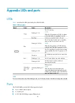
 describes the LEDs provided by the WA2610i-GN. 

Table 3


LED description 

Mark Color 

Status 

Description 


Green 

Flashing at 1 Hz  

The AP is booting. 

NOTE: 

When the AP operates as a fit AP, it is always 

in this state before it is registered to an AC. 

Breathing 

A client is connected to the 2.4G port. 

Blue 

Flashing at 0.25 Hz 

The AP has been booted, and is in standby 
state (no client is connected to the AP). 

NOTE: 

When the AP operates as a fit AP, this state 

indicates the AP has been registered to an AC. 

Flashing at 4 Hz 

The AP is updating its system software image 
(only available when the AP operates as a fit 
AP). 

Red 

Steady on 

An initialization exception has occurred to the 
AP. 

Flashing at 1 Hz 

The AP cannot detect any radio interface. 

Flashing at 8 Hz 

An Ethernet port or radio interface is 
operating abnormally. 

Alternating 
green and 
blue 

Alternating flashing at 1 
Hz 

Blinking mode. 

NOTE: 

When the fit AP associated with the AC 

receives the blinking command sent by the AC, 
it flashes green and blue to show the fit AP has 

been associated with the AC. 


NOTE:  

For more information about the blinking mode, see 

WX Series Access Controllers Configuration Guides.


Ports 

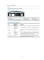
The WA2610i-GN provides the following external ports: 


Two 2.4 GHz antenna ports 


A console port 


A 10/100/1000 Mbps copper Ethernet port 

Summary of Contents for WA2610i-GN

Page 1: ...H3C WA2610i GN Access Point Installation Guide Hangzhou H3C Technologies Co Ltd http www h3c com Document version APW102 20130320...

Page 2: ...d All other trademarks that may be mentioned in this manual are the property of their respective owners Notice The information in this document is subject to change without notice Every effort has bee...

Page 3: ...GUI conventions Convention Description Boldface Window names button names field names and menu items are in Boldface For example the New User window appears click OK Multi level menus are separated b...

Page 4: ...hardware installation software upgrading and software feature configuration and maintenance documentation Products Solutions Provides information about products and technologies as well as solutions T...

Page 5: ...ting the power supply 10 Check before power on 11 Local power supply 11 PoE power supply 12 Check after power on 12 Connecting the AP to the network 12 Checking the network connection for the fit AP 1...

Page 6: ...fat AP to provide wireless access for WLAN users Figure 1 Deployment of the AP on hotspots fit AP Figure 2 Deployment of the AP on hotspots fat AP Core equipment room RADIUS server Wireless NMS Switc...

Page 7: ...2 Table 1 Basic configuration Dimensions H W D Weight Max power Enclosure Protocol Power supply 160 160 50 mm 6 30 6 30 1 97 in 328 g 11 57 oz 12 95 W Plastic 802 11b g n Local power supply 802 3af...

Page 8: ...adequate safety measures to avoid bodily injury and access point damage Make sure that the ground is dry and flat and anti slip measures are in place Keep the chassis clean and dust free Do not place...

Page 9: ...in to the AP see Logging in to the fat AP Figure 3 Installation flowchart Check before installation Before you install an AP check the following Connect the power cord and connect the AP to the netwo...

Page 10: ...ace where water seeping water soaking and condensing occur Prevent water or moisture from entering the APs CAUTION If part of the power line is routed outdoors use a power strip with lightning protect...

Page 11: ...cations and sizes in mm 1 Hook 2 Mounting hole 3 Clip 4 Mounting clip CAUTION Connect the AP to the network by using an Ethernet cable and then install the AP to the wall mounting bracket when you mou...

Page 12: ...mmer until it is all flush with the wall surface Figure 8 Fix the anchor to the wall 3 Align the holes in the wall mounting bracket with the anchors and insert screws through the installation holes in...

Page 13: ...ct the AP to the network by using an Ethernet cable 6 Align the mounting keyhole on the rear of the AP over the hook on the wall mounting bracket 7 Mount the AP on the hook on the wall mounting bracke...

Page 14: ...a weight of at least 5 kg 1 1 02 lb Do not use this method to mount the AP to a location made of low intensity materials such as a plaster ceiling If this installation method is required in such an en...

Page 15: ...the ceiling From above the ceiling fasten the hex nuts to the hex head bolts to fix the mounting bracket to the ceiling 3 Connect the AP to the network by using an Ethernet cable 4 Install the AP to t...

Page 16: ...ply Check before power on Check the following items before you power on the AP The power supply is well grounded when the AP adopts local power supply The PoE power supply is well grounded when the AP...

Page 17: ...owering on the AP check the AP status LED For more information about AP LEDs see Appendix LEDs and ports Connecting the AP to the network APs can access the Internet or metropolitan area network MAN t...

Page 18: ...fm AP Name State Model Serial ID ap1 R M WA2610i GN 219801A0CLC118000435 AC Checking the network connection for the fat AP When the AP operates as a fat AP use the ping command to ping the uplink netw...

Page 19: ...he device to remotely manage and maintain it Logging in through web You can log in to the web interface of the device to remotely manage and maintain it Logging in through the console port Prepare the...

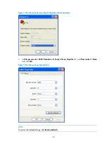
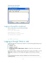
Page 20: ...parameters for example on a Windows XP HyperTerminal 1 Select Start All Programs Accessories Communications HyperTerminal The Connection Description dialog box appears 2 Enter the name of the new conn...

Page 21: ...he HyperTerminal connection 4 Set Bits per second to 9600 Data bits to 8 Parity to None Stop bits to 1 and Flow control to None and click OK Figure 18 Set the serial port parameters NOTE To restore th...

Page 22: ...By default the Telnet and web functions are enabled You can use the following default settings to log in to the web interface Username admin Password h3capadmin Management IP address of VLAN interfac...

Page 23: ...ting its system software image only available when the AP operates as a fit AP Red Steady on An initialization exception has occurred to the AP Flashing at 1 Hz The AP cannot detect any radio interfac...

Page 24: ...02 1 1b IEEE802 1 1g IEEE802 1 1n The antenna ports are provided for 2 4 GHz single RF antennas 48V DC N A The local power port is used for 48 VDC power supply to the device ETHERNET IEEE802 3 IEEE802...

Page 25: ...at AP 13 Checking the network connection for the fit AP 12 L Local power supply 1 1 Logging in through the console port 17 M Mounting the AP on a ceiling 9 Mounting the AP on a table 5 Mounting the AP...

Reviews: