background image

Examples provided in this document 

Examples in this document might use devices that differ from your device in hardware model, 
configuration, or software version. It is normal that the port numbers, sample output, screenshots, 
and other information in the examples differ from what you have on your device. 

Obtaining documentation 

To access the most up-to-date H3C product documentation, go to the H3C website at 

To obtain information about installation, configuration, and maintenance, click 

To obtain software version information such as release notes, click 


Technical support 

service@h3c.com 

Documentation feedback 

You can e-mail your comments about product documentation to info@h3c.com.  

We appreciate your comments. 


Summary of Contents for WA5620i-ACN

Page 1: ...H3C WA5620i ACN Access Point Installation Guide New H3C Technologies Co Ltd http www h3c com hk Document version 6W101 20170414 ...

Page 2: ...er trademarks that may be mentioned in this manual are the property of their respective owners Notice The information in this document is subject to change without notice Every effort has been made in the preparation of this document to ensure accuracy of the contents but all statements information and recommendations in this document do not constitute the warranty of any kind express or implied E...

Page 3: ...ents arguments that you replace with actual values Square brackets enclose syntax choices keywords or arguments that are optional x y Braces enclose a set of required syntax choices separated by vertical bars from which you select one x y Square brackets enclose a set of optional syntax choices separated by vertical bars from which you select one or none x y Asterisk marked braces enclose a set of...

Page 4: ... topology icons Convention Description Represents a generic network device such as a router switch or firewall Represents a routing capable device such as a router or Layer 3 switch Represents a generic switch such as a Layer 2 or Layer 3 switch or a router that supports Layer 2 forwarding and other Layer 2 features Represents an access controller a unified wired WLAN module or the access controll...

Page 5: ...ocumentation To access the most up to date H3C product documentation go to the H3C website at http www h3c com hk To obtain information about installation configuration and maintenance click http www h3c com hk Technical_Documents To obtain software version information such as release notes click http www h3c com hk Software_Download Technical support service h3c com http www h3c com hk Documentat...

Page 6: ...ent 3 Installing the AP 4 Check before installation 4 Determining the installation position 4 Installing the AP 5 Mounting the AP on a wall 5 Installing the AP on a ceiling 7 Connecting the AP to a power supply 10 Connecting a PoE power supply 10 Connecting the local power supply 10 Check after power on 11 Connecting the AP to the network 11 Verifying network connection for the fit AP 11 ...

Page 7: ...ttings are configured on the access controller modules or access controllers Figure 1 Deployment of WA5620i ACN APs Table 1 H3C WA5620i ACN specifications Item Specification Protocol IEEE 802 11a b g n ac Dual radio Built in antennas 2 4 G antenna gain 4 dBi 5 G antenna gain 4 dBi Power consumption 12 5 to 25 W Dimensions H W D 52 220 227 mm 2 05 8 66 8 94 in Weight 1 06 kg 2 34 lb ...

Page 8: ...ake adequate safety measures to avoid injury and AP damage Place the AP in a dry and flat location and take anti slip measures Keep the AP clean and dust free Do not place the AP in a moist area and avoid liquid surrounding the AP Keep the AP and installation tools away from walkways Temperature and humidity requirements Item Specification Operating temperature indoor 10 C to 55 C 14 F to 131 F St...

Page 9: ...nd equipment When installing the AP you may need the following tools Prepare these tools and equipment yourself Needle nose pliers Wire stripping pliers Diagonal pliers Marker Percussion drill with matching drills Rubber hammer Phillips screwdriver ...

Page 10: ...he AP MAC address and serial number marked on the rear of the AP for future use NOTE Use a category 5e cable to connect the AP s 2 5 GE port For the interface to operate at 2500 Mbps use an H3C switch that provides a 2 5 GE interface Use a category 5 cable to connect the AP s GE port The auto negotiated transmission rate is 1000 or 100 Mbps Determining the installation position You can mount the A...

Page 11: ...g arrester user supplied is installed on the AP for cabling outdoors The AP must be over 5 meter away from 3G and 4G stations and antennas Installing the AP Mounting the AP on a wall 1 Align the screw hole in the AP bracket with the screw hole in the AP rear Use the M4 10 screw to secure the AP bracket to the AP Figure 3 Attaching the AP bracket to the AP rear 2 Mark the installation holes on the ...

Page 12: ... mm 1 18 in in the marked locations as shown in Figure 6 Figure 6 Drilling holes in the wall 4 Insert a wall anchor into each hole and tap the wall anchor with a rubber hammer until it is all flush with the wall surface as shown in Figure 7 Figure 7 Hammering the anchor 73 mm 2 87 in 69 4 mm 2 73 in 69 4 mm 2 73 in ...

Page 13: ...o the LAN by using Ethernet cables 7 Align the AP at a 45 degree angle with the mounting bracket and rotate the AP clockwise until it clicks into place as shown in Figure 9 Figure 9 Attaching the AP to the wall mounting bracket Installing the AP on a ceiling CAUTION The ceiling for installing the AP must be less than 18 mm 0 71 in in thickness and can bear a load of 5 kg 11 02 lb As a best practic...

Page 14: ...llation holes on the ceiling by using the mounting bracket 3 Drill holes with a diameter of 5 mm 0 197 in in the marked positions as shown in Figure 11 Figure 11 Drilling holes in the ceiling 4 Insert the M4 30 pan head screws through the mounting holes in the mounting bracket and the holes in the ceiling Fasten washers and nuts at the other side of the ceiling to attach the mounting bracket to th...

Page 15: ...e LAN by using Ethernet cables 6 Align the AP with the mounting bracket and rotate the AP clockwise until it clicks into place as shown in Figure 13 Figure 13 Attaching the AP to the ceiling mounting bracket 7 Verify that the AP is securely installed to prevent it from falling off ...

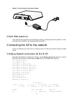
Page 16: ...ing a PoE power supply Use an Ethernet cable to connect the Ethernet interface that supports PoE on the AP to a PoE switch Figure 14 Connecting a PoE power supply Connecting the local power supply No AC DC adapter and power cord are provided with the AP Prepare them yourself if required Table 2 AC DC adapter specifications Item Specification Input 100 VAC to 240 VAC Output 54V at 0 74 A You can po...

Page 17: ...the display wlan ap all command on the AC that connects to the fit AP If the AP status is R M the AP is connected to the network AC display wlan ap all Total number of APs 1 Total number of connected APs 1 Total number of connected manual APs 1 Total number of connected auto APs 0 Total number of connected common APs 0 Total number of connected WTUs 0 Total number of inside APs 0 Maximum supported...

Page 18: ...i Contents Appendix LEDs and ports 1 LEDs 1 Ports 2 ...

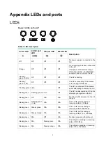
Page 19: ...addresses and is attempting to discover an AC Steady green Flashing green in turn Off The AP has discovered an AC and is attempting to register on the AC Steady green Off N A N A No link or traffic is present on the 2 5 GE port Steady green Flashing green 1 Hz N A N A The 2 5 GE port is sending or receiving data at 2 5 Gbps Steady green Steady green N A N A The 2 5 GE port is sending or receiving ...

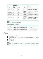
Page 20: ...dios NOTE N A in Table 1 represents any LED status Table 2 Reset button description Pressing time LED status Description 0 to 5 seconds The power 2 5 GE port and GE port LEDs are steady green and the WLAN LED is off The AP is reset 5 to 15 seconds The power 2 5 GE port and GE port LEDs are flashing green at 0 5 Hz and the WLAN LED is off Factory settings are restored Ports The AP provides the foll...

Page 21: ...act as an uplink interface to access the Internet or MAN and as a PoE port at the same time It is represented by interface Smartrate Ethernet1 0 1 GE IEEE802 3 IEEE802 3u IEEE802 3at IEEE802 3af The 10 100 1000 Mbps copper Ethernet port can act as an uplink interface to access the Internet or MAN and as a PoE port at the same time It is represented by interface GE1 0 2 DC 48V N A The port receives...

Reviews: