background image


6-6 

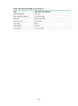
Table6-2 SFP-XG-CPRI-LR-SM1310 specifications 

Item 

SFP-XG-CPRI-LR-SM1310 

Central wavelength 

1310 nm 

Max transmission distance 

10 km (6.21 miles) 

Data rate 

4920 to 10310 Mb/s 

Connector type 

LC connector 

Fiber mode 

SMF 

Fiber diameter 

9/125 

μm 

Output power 

–8.2 to +0.5 dBm 


Summary of Contents for WA6628E-T

Page 1: ...H3C WA6628E T Access Point Installation Guide New H3C Technologies Co Ltd http www h3c com Document version 5W100 20201125 ...

Page 2: ...respective owners Notice The information in this document is subject to change without notice All contents in this document including statements information and recommendations are believed to be accurate but they are presented without warranty of any kind express or implied H3C shall not be liable for technical or editorial errors or omissions contained herein Environmental protection This produc...

Page 3: ...ents that are optional x y Braces enclose a set of required syntax choices separated by vertical bars from which you select one x y Square brackets enclose a set of optional syntax choices separated by vertical bars from which you select one or none x y Asterisk marked braces enclose a set of required syntax choices separated by vertical bars from which you select a minimum of one x y Asterisk mar...

Page 4: ...as a Layer 2 or Layer 3 switch or a router that supports Layer 2 forwarding and other Layer 2 features Represents an access controller a unified wired WLAN module or the access controller engine on a unified wired WLAN switch Represents an access point Represents a wireless terminator unit Represents a wireless terminator Represents a mesh access point Represents omnidirectional signals Represents...

Page 5: ...Documentation feedback You can e mail your comments about product documentation to info h3c com We appreciate your comments ...

Page 6: ...ecting an M12 cable 2 8 Connecting the power cord 2 9 Connecting the AP to the network 2 11 Verifying network connectivity when the AP operates in fit mode 2 11 Verifying network connectivity when the AP operates in fat mode 2 12 3 Accessing the AP 3 1 Login from the console port 3 1 Connecting the AP to a configuration terminal from the console port 3 1 Setting parameters for the configuration te...

Page 7: ...cut off power immediately in case of an emergency Before you install remove move or service the AP turn off power to the AP and remove the power cord and cables from the AP When performing electrical operations you must comply with local laws and regulations The relevant staff must have corresponding qualifications To avoid electric shocks use a yellow green grounding cable to ground the AP Before...

Page 8: ...d Figure1 2 Installation tools Cage nut user supplier M6 screw user supplied Wall mount brackets user supplied Mounting brackets user supplied M4 screw user supplied Grounding cable user supplied 4 4 8 WAGO power connector Load optional Lightning arrester optional Marker Nonslip gloves Torque screwdriver Heat gun Needle nose pliers Wire stripper Wire crimper Wrench ESD wrist strap PH 2 PH 3 ...

Page 9: ... Record the MAC address and serial number of the AP for future use Determining the installation position When selecting an installation position for the AP follow these guidelines Keep the AP away from electronic equipment or devices such as microwave ovens that might generate radio frequency noise Start Install the AP End Pre installation tasks Connect the grounding cable Connect the power cord W...

Page 10: ...ineers Ensure that the AP is installed in a weak electric box or device with a protection level of IP54 or higher Mounting the AP The AP can be installed only indoors You can mount the AP on a wall or in a rack Installation brackets Wall mount brackets are required for wall mounting the AP Mounting brackets are required for rack mounting the AP No wall mount brackets or mounting brackets are provi...

Page 11: ...nting the AP on a wall 1 Use M4 screws to attach the wall mount brackets to the AP and fasten the screws Figure2 4 Attaching the wall mount brackets to the AP 2 Use M6 screws to attach the AP to a power distribution cabinet M4 1 4N m PH2 ...

Page 12: ...akes good skin contact and is reliably grounded 2 Make sure the rack is stable and reliably grounded 3 Use the mounting brackets to mark the cage nut installation positions on the rack posts and then install cage nuts Figure2 6 Installing cage nuts 4 Use the M4 mounting bracket screws to attach the mounting brackets to the AP 2 M6 5N m PH3 1U ...

Page 13: ...h one hand and holding the front of the AP with the other gently push the AP into the rack Then use M6 rack screws and cage nuts to attach the mounting brackets to the rack posts Make sure the AP is attached securely to the rack Figure2 8 Mounting the AP in a rack M4 1 4N m PH2 M6 5N m PH3 ...

Page 14: ...crew from the grounding hole in the rear panel of the AP 2 Attach the grounding screw to the ring terminal of the grounding cable 3 Use a Phillips screwdriver to fasten the grounding screw into the grounding hole 4 Connect the other end of the grounding cable to the grounding cable in the train compartment or the power distribution cabinet Figure2 9 Connecting the grounding cable Connecting RF cab...

Page 15: ...a port to an external antenna To connect an RF cable 1 Remove the weatherproof cap from the antenna port on the AP 2 Connect a lightning arrester to the antenna port 3 Connect the RF cable to the lightning arrester Figure2 10 Connecting an RF cable 4 Install a load for each unused antenna port Figure2 11 Installing a load for an antenna port ...

Page 16: ...des and push the end without the bail latch gently into the port until it snaps into place 3 Identify the Rx and Tx ports on the transceiver module Use the optical fiber with LC connectors to connect the Rx port and Tx port on the AP to the Tx port and Rx port on the peer device respectively 4 Observe the port LED to verify link connectivity If the LED is on the link is connected If the LED is off...

Page 17: ...e AP The AP supports AC or DC power input See Table2 2 for the power input specifications Table2 2 Power input specifications Item Specification DC power input 70 V to 130 V AC power input 100 V to 240 V 50 60 Hz Connecting the power cord to a Wago connector 1 Strip 10 mm 0 39 in of insulation off one end of the power cord 2 Use a flathead screwdriver to press down the movable tab in the target ho...

Page 18: ...ing a DC power cord 1 Make sure the AP is reliably grounded 2 Connect one end of the DC power cord to the power port on the AP and the other end to a local power source Figure2 15 Connecting a DC power cord 1 3 2 4 Power port on the AP Vin Vin Name 1 Pin No 2 PE 3 2 3 1 ...

Page 19: ...net switch Verifying network connectivity when the AP operates in fit mode When the AP operates in fit mode all its settings are configured on the AC Execute the display wlan ap all command on the AC If the AP status in the command output is R M the AP has associated with the AC and connected to the network AC display wlan ap all Total number of APs 1 Total number of connected APs 1 Total number o...

Page 20: ...P name AP ID State Model Serial ID ap1 1 R M WA6628E T 219801A2ES8209E00014 Verifying network connectivity when the AP operates in fat mode When the AP operates in fat mode use the ping command on it to ping the uplink network device If the ping operation succeeds the AP is connected to the network successfully ...

Page 21: ...d a DB 9 connector at the other end A configuration terminal It can be a standard character terminal with an RS 232 port or a PC Connecting the AP to a configuration terminal from the console port CAUTION The serial ports on PCs do not support hot swapping To connect a PC to an operating device first connect the PC end To disconnect a PC from an operating device first disconnect the device end If ...

Page 22: ...rrectly to the configuration terminal and the configuration terminal parameters are configured correctly Then power on the AP You can see the following information on the configuration terminal System is starting Booting Normal Extend BootWare System application is starting Startup configuration file does not exist User interface con0 is available Press ENTER to get started Login from the Web inte...

Page 23: ...ons Table4 1 Technical specifications Item Specification Dimensions H W D 40 260 210 mm 1 57 10 24 8 27 in Weight 2 4 kg 5 29 lb Antenna External antenna Power consumption 8 W to 40 W Radios 2 Protocols and standards IEEE802 11a b g n ac ax ...

Page 24: ...el of the AP 1 Grounding screw 2 Power port 3 10 100 1000M Ethernet port with an M12 connector 4 10 GE Ethernet fiber port 5 Console port 6 5G antenna port Figure5 2 Ports on the rear panel of the AP 1 2 4G 5G antenna port 2 10 100 1000M Ethernet port with an M12 connector 3 Grounding screw Table5 1 Port descriptions Port Standards and protocols Description Console port RS EIA 232 Used only for de...

Page 25: ...e AP to an uplink device for Internet or MAN access It is represented by interface number XGE1 0 1 in the MAP file and Ten GigabitEthernet 1 for configuration on the AC 5G antenna port IEEE802 11a IEEE802 11an IEEE802 11ac IEEE802 11ax Used for connecting to a 5G antenna 2 4G 5G antenna port IEEE802 11b IEEE802 11g IEEE802 11gn IEEE802 11gac IEEE802 11a IEEE802 11an IEEE802 11ac IEEE802 11ax Used ...

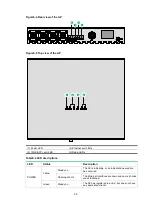
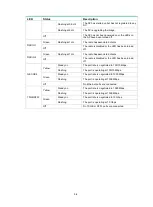
Page 26: ...s Table5 2 LED descriptions LED Status Description POWER Yellow Steady on The AP is initializing or an initialization exception has occurred Flashing at 2 Hz The Ethernet interfaces are down and no mesh links are established Green Steady on The AP has registered to an AC but does not have any associated clients 2 1 4 3 1 4 2 3 ...

Page 27: ...adio has associated clients Off The radio is disabled or the LED has been turned off GE1 GE2 Yellow Steady on The port rate is negotiated to 100 10 Mbps Flashing The port is operating at 100 10 Mbps Green Steady on The port rate is negotiated to 1000 Mbps Flashing The port is operating at 1000 Mbps Off No Ethernet ports are connected 10GE SFP Yellow Steady on The port rate is negotiated to 1000 Mb...

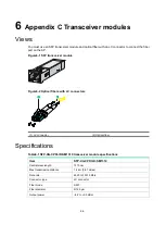
Page 28: ...odule Figure6 2 Optical fibers with LC connectors 1 LC connector 2 Optical fiber Specifications Table6 1 SFP XG CPRI IR SM1310 transceiver module specifications Item SFP XG CPRI IR SM1310 Central wavelength 1310 nm Max transmission distance 1 4 km 0 87 miles Data rate 4920 to 10310 Mb s Connector type LC connector Fiber mode SMF Fiber diameter 9 125 μm Output power 8 2 to 0 5 dBm 1 2 ...

Page 29: ... specifications Item SFP XG CPRI LR SM1310 Central wavelength 1310 nm Max transmission distance 10 km 6 21 miles Data rate 4920 to 10310 Mb s Connector type LC connector Fiber mode SMF Fiber diameter 9 125 μm Output power 8 2 to 0 5 dBm ...

Reviews: